MT8940 데이터 시트보기 (PDF) - Mitel Networks
부품명
상세내역
일치하는 목록
MT8940 Datasheet PDF : 16 Pages
| |||
ISO-CMOS MT8940
Applications
The following figures illustrate how the MT8940 can
be used in a minimum component count approach to
providing the timing and synchronization signals for
the Mitel T1 and CEPT interfaces, and the ST-BUS.
The hardware selectable modes and the
independent control over each PLL adds flexibility to
the interface circuits. It can be easily reconfigured to
provide the timing and control signals for both at the
master and slave ends of the link.
Synchronization and Timing Signals for the T1
Transmission Link
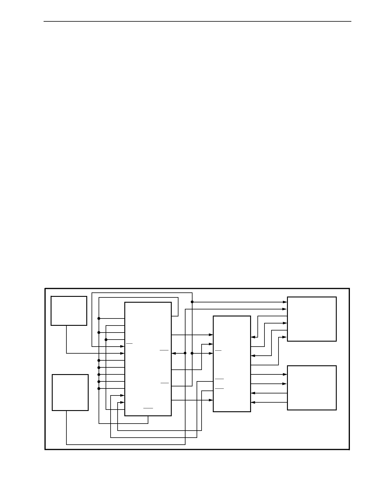
Figures 4 and 5 show examples of how to generate
the timing signals for the master and slave ends of a
T1 link.
At the master end of the link (Figure 4), DPLL #2 is
the source of the ST-BUS signals derived from the
4.096 MHz system clock. The frame pulse output is
looped back to DPLL #1 (in NORMAL mode), which
locks to it to generate the T1 line clock. The timing
relationship between the 1.544 MHz T1 clock and
the 2.048 MHz ST-BUS clock meets the
requirements of the MH89760/760B. The crystal
clock at 12.355 MHz is used by DPLL #1 to generate
the 1.544 MHz clock, while DPLL #2 uses the 4.096
MHz system clock to provide the ST-BUS timing
signals. The ST-BUS signals can also be obtained
from DPLL #2 in FREE-RUN mode, using a crystal
clock at 16.388 MHz instead of 4.096 MHz system
clock. The uncommitted NAND gate converts the
received signals, RxA and RxB of the MH89760 to a
single Return to Zero (RZ) input for the clock
extraction circuits of the MH89760. This is not
required for the MH89760B. The generated ST-BUS
signals can be used to synchronize the system and
the switching equipment at the master end.
At the slave end of the link (Figure 5) both the DPLLs
are in NORMAL mode with DPLL #2 providing the
ST-BUS timing signals locked to the 8 kHz frame
pulse (E8Ko) extracted from the received signal on
the T1 line. The regenerated frame pulse is looped
back to DPLL #1 to provide the T1 line clock as at
the master end. The 12.355 MHz and 16.388 MHz
crystal clock sources are necessary for DPLL #1 and
#2.
Synchronization and Timing Signals for the
CEPT Transmission Link
The MT8940 can be used to provide the timing and
synchronization signals for the MH89790/790B,
MITEL’s CEPT(30+2) digital trunk interface hybrid.
Since the operational frequencies of the ST-BUS and
the CEPT primary multiplex digital trunk are same,
only DPLL #2 is required to achieve synchronization
between the two.
Figures 6 and 7 show how the MT8940 can be used
to synchronize the ST-BUS and the CEPT
transmission link at the master and slave ends,
respectively.
Crystal Clock
(12.355 MHz
±100 ppm)
4.096 MHz
System Clock
(ST-BUS
compatible)
MT8940
MS0
MS1
MS2
MS3
F0i
C12i
ENCV
C8Kb
C16i
ENC4o
ENC2o
Ai
Bi
VSS RST
VDD
CV
C4b
C2o
F0b
Yo
MH89760
C1.5i
C2i
F0i
RxA
RxB
RxD
DSTi
DSTo
CSTi
CSTo
TxT
TxR
RxT
RxR
TRANSMIT
RECEIVE
MT8980/81
ST-BUS
SWITCH
T1
LINK
(1.544 Mbps)
MODE OF OPERATION FOR THE MT8940
DPLL #1 - NORMAL (MS0 = X; MS1 = 0)
DPLL #2 - OVERRIDE THE MAJOR MODES (MS2 = 1; MS3 = 0)
Figure 4 - Synchronization at the Master End of the T1 Transmission Link
3-33
Share Link: 