MT8940 데이터 시트보기 (PDF) - Mitel Networks
부품명
상세내역
일치하는 목록
MT8940 Datasheet PDF : 16 Pages
| |||
MT8940 ISO-CMOS
F0b (refer to Figure 15). Otherwise, the input on pin
F0b will have no bearing on the operation of DPLL
#2, unless it is in FREE-RUN mode as selected by
MS0 and MS1. In FREE-RUN mode, the input on
F0b is treated the same way as the C8Kb input in
NORMAL mode. The frequency of the input signal on
F0b should be 16 kHz for DPLL #2 to provide the ST-
BUS compatible clocks at 4.096 MHz and 2.048
MHz.
When MS2 is HIGH, the F0b pin provides the ST-
BUS frame pulse output locked to the 8kHz internal
or external signal as determined by the other mode
select pins MS0, MS1 and MS3.
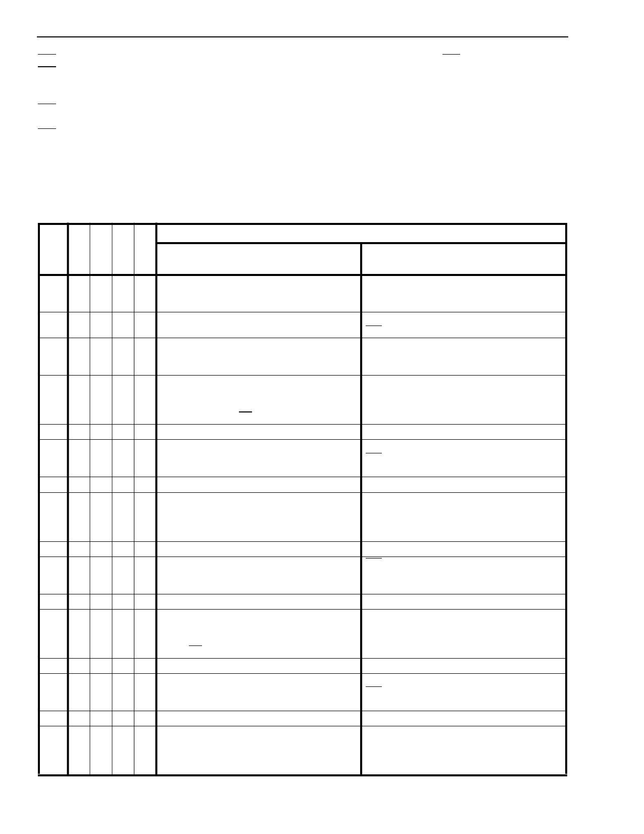
Table 4 summarizes the modes of the two DPLLs. It
should be noted that each of the major modes
selected for DPLL #2 can have any of the minor
modes, although some of the combinations are
functionally similar. The required operation of both
DPLL#1 and DPLL#2 must be considered when
determining MS0-MS3.
M
O
D
E
MS MS MS MS
0123
#
DPLL #1
Operating Modes
DPLL #2
0 0 0 0 0 NORMAL MODE
Properly phase related External 4.096 MHz
clock and 8 kHz frame pulse provide the ST-
BUS clock at 2.048 MHz.
1 0 0 0 1 NORMAL MODE
2 0 0 1 0 NORMAL MODE
NORMAL MODE
F0b is an input but has no function in this mode.
External 4.096 MHz provides the ST-BUS clock
and Frame Pulse at 2.048 MHz and 8 kHz,
respectively.
NORMAL MODE:
3
0
0
1
1
Provides the T1 (1.544 MHz) clock
synchronized to the falling edge of the
input frame pulse (F0i).
NORMAL MODE:
Provides the CEPT/ST-BUS compatible timing
signals locked to the 8 kHz input signal (C8Kb).
4 0 1 0 0 DIVIDE-1 MODE
Same as mode ‘0’.
5 0 1 0 1 DIVIDE-1 MODE
6 0 1 1 0 DIVIDE-1 MODE
SINGLE CLOCK-1 MODE
F0b is an input, but has no function in this
mode.
Same as mode 2.
DIVIDE-1 MODE:
7
0
1
1
1
Divides the CVb input by 193. The divided
output is connected to DPLL #2.
8 1 0 0 0 NORMAL MODE
SINGLE CLOCK-1 MODE:
Provides the CEPT/ST-BUS compatible timing
signals locked to the 8 kHz internal signal
provided by DPLL #1.
Same as mode ‘0’.
NORMAL MODE
9 1001
10 1 0 1 0 NORMAL MODE
F0b is an input and DPLL #2 locks on to
it only if it is at 16 kHz to provide the ST-BUS
control signals.
Same as mode 2.
NORMAL MODE
FREE-RUN MODE:
11
1
0
1
1
Provides the T1 (1.544 MHz) clock
synchronized to the falling edge of input frame
Provides the ST-BUS timing signals with no
external inputs except the master clock.
pulse (F0i).
12 1 1 0 0 DIVIDE-2 MODE
Same as mode ‘0’.
DIVIDE-2 MODE
13 1 1 0 1
14 1 1 1 0 DIVIDE-2 MODE
SINGLE CLOCK-2 MODE:
F0b is an input, but has no function in this
mode.
Same as mode 2.
DIVIDE-2 MODE:
SINGLE CLOCK-2 MODE:
15
1
1
1
1
Divides the CVb input by 256. The divided
output is connected to DPLL#2.
Provides the CEPT/ST-BUS compatible timing
signals locked to the 8 kHz internal signal
provided by DPLL #1.
Table 4. Summary of Modes of Operation - DPLL #1 and #2
3-32
Share Link: 