NJU6635CH 데이터 시트보기 (PDF) - Japan Radio Corporation
부품명
상세내역
일치하는 목록
NJU6635CH Datasheet PDF : 33 Pages
| |||
NJU6635
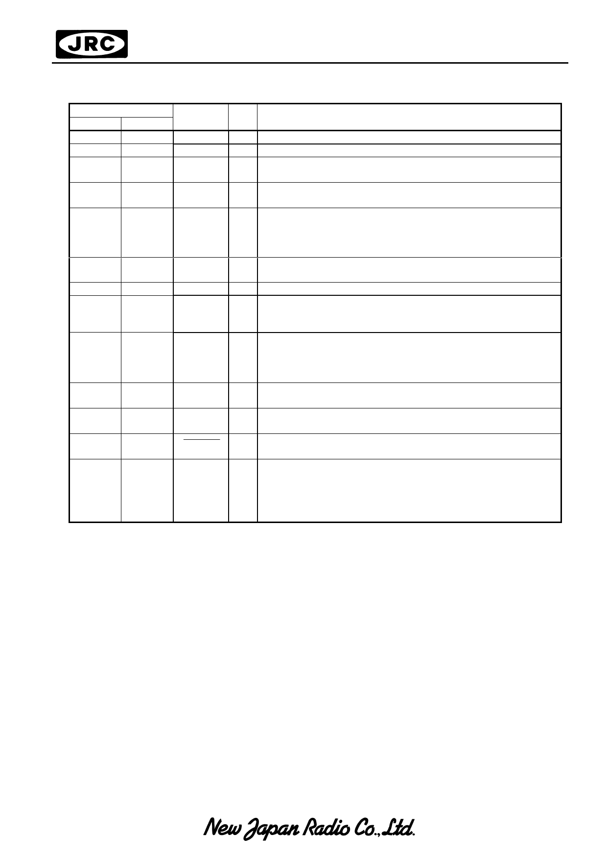
s TERMINAL DESCRIPTION
PAD No.
SYMBOL I/O
A mode B mode
4–9
4–9
VDD, VSS
–
10 – 14 10 – 14 V2, V3, V5 –
2
2
OSC1
I
3
3
OSC2
O
16
16
RS
I
17
17
R/W
I
18
18
E
I
26 – 23 26 – 23 DB7 – DB4 I/O
19 – 22 19 – 22 DB3 – DB0 I/O
32 – 39, 133 – 126, COM1 – O
126 – 133 39 – 32
COM16
43 – 122 122 – 43 SEG1 – O
SEG80
15
15
RESET
I
1,
27 – 31,
40 – 42,
1,
DUMMY1 O
27 – 31,
–
40 – 42, DUMMY15
123 – 125, 123 – 125,
134 – 137 134 – 137
FUNCTION
Power Source : VDD = +5V, GND : VSS = 0V
LCD driving Power Source
Oscillation Frequency Adjustment Terminals. Normally Open.
(Oscillation C and R are Incorporated, Osc Freq.=540kHZ)
Oscillation Frequency Adjustment Terminals. Normally Open.
This terminal also operates as the clock frequency monitor.
Resister selection signal Input
"0":Instruction Resister (Writing)
Busy Flag
(Reading)
"1":Data Register (Writing / Reading)
Read/Write selection signal Input
"0":Write "1":Read
Read/write activation Signal Input
3-state Data Bus(Upper) to transfer the data between MPU and
NJU6635.
DB7 is also used for the Busy Flag reading.
3-state Data Bus(Lower) to transfer the data between MPU and
NJU6635.
In serial and 4bit parallel mode, these terminals are not used
and should be open.
LCD Common driving signal Terminals
LCD segment driving signal Terminals
Reset Terminal. When the “L” level Input over than 1.2ms to
this terminal, the system will be reset.(fOSC=540kHz)
Dummy Terminal
These terminals are electrically open.
Share Link: 