NJU6635CH 데이터 시트보기 (PDF) - Japan Radio Corporation
부품명
상세내역
일치하는 목록
NJU6635CH Datasheet PDF : 33 Pages
| |||
NJU6635
(2)Power on Initialization by internal circuits
(2-1) Initialization By internal Reset circuits
The NJU6635 is initialized automatically by the internal power on initialization circuits when the power
is turned on. In the internal power on initialization, following instructions are executed.
During the internal power on initialization, the busy flag (BF) is “1” and this status is kept 10ms after
VDD = 4.5V.
Initialization flow is shown below:
Clear Display
Function Set
DL=1
A=0
M0=0
M1=0
E=0
:8-bit long interface data
:Addressing mode 1
:A mode
:32-character 1-line
:Normal Display mode
Display On/Off
Control
D=0 :Display Off
C=0 :Cursor Off
B=0 :Cursor Blink Off
Entry Mode Set
I/D=1 :Increment by 1
S=0 :No Shift
Note) If the condition of power supply rise time described in the Electrical Characteristics is not satisfied, the
internal Power on initialization Circuits will not operate and initialization will not be performed.
In this case, the initialization by MPU software is required.
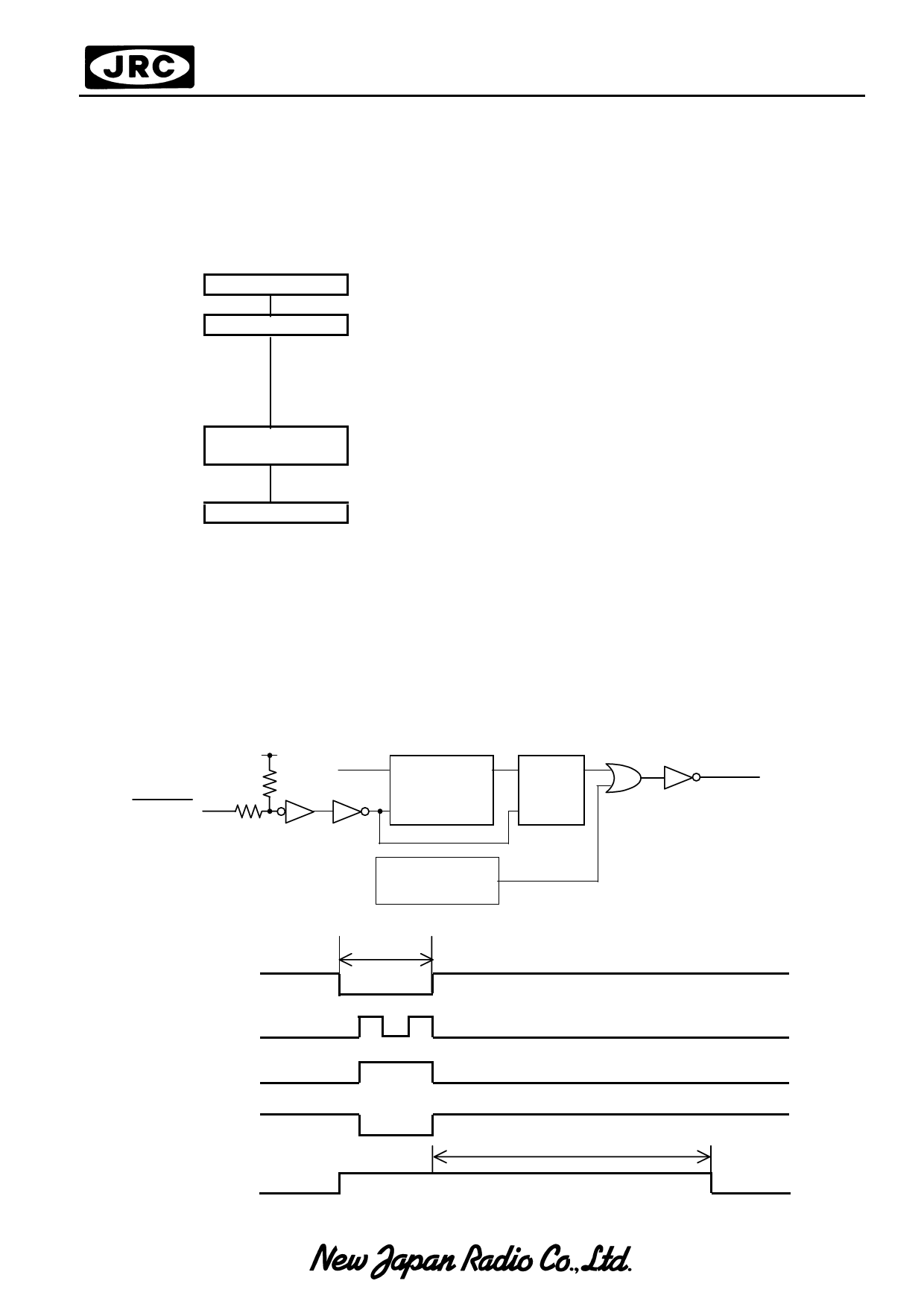
(2-2) Initialization By Hardware
The NJU6635 incorporates RESET terminal to initialize the all system. When the “L” level input over
than 1.2ms to the RESET terminal, the reset sequence is executed. In this time, the busy signal output
during 10ms after RESET terminal goes to “H”.
• RESET operation
RESET
System clock
C
Q
Counter
RST
CQ
RST
RS-F/F
System RESET
Power No
RESET
• Operation timing
External Reset
Signal
Over 1.2ms
Counter Output
RS-F/F Output
Internal Reset
Signal
BUSY
10ms
Share Link: 