IDT72510L25J 데이터 시트보기 (PDF) - Integrated Device Technology
부품명
상세내역
일치하는 목록
IDT72510L25J
Integrated Device Technology

IDT72510L25J Datasheet PDF : 32 Pages
| |||
IDT72510, IDT72520
BUS MATCHING BIDIRECTIONAL FIFO
COMMERCIAL TEMPERATURE RANGE
FUNCTIONAL DESCRIPTION
IDT’s BiFIFO family is versatile for both multiprocessor
and peripheral applications. Data can be sent through both
FIFO memories concurrently, thus freeing both processors
from laborious direct memory access (DMA) protocols and
frequent interrupts.
Two full 18-bit wide FIFOs are integrated into the IDT
BiFIFO, making simultaneous data exchange possible. Each
FIFO is monitored by separate internal read and write point-
ers, so communication is not only bidirectional, it is also
totally independent in each direction. The processor con-
nected to Port A of the BiFIFO can send or receive mes-
sages directly to the Port B device using the BiFIFO’s 9-bit
bypass path.
The BiFIFOs can be used in three different bus configura-
tions: 18 bits to 9 bits, 36 bits to 9 bits and 36 bits to 18 bits.
One BiFIFO can be used for the 18- to 9-bit configuration,
and two BiFIFOs are required for 36- to 9-bit or 36- to 18-bit
configurations. Bits 11 and 12 of Configuration Register 5
determine the BiFIFO configuration (see Table 11 for
Configuration Register 5 format).
The microprocessor or microcontroller connected to Port
A controls all operations of the BiFIFOs. Thus, all Port A
interface pins are inputs driven by the controlling processor.
Port B can be programmed to interface either with a second
processor or a peripheral device. When Port B is programmed
in processor interface mode, the Port B interface pins are
inputs driven by the second processor. If a peripheral device
is connected to the BiFIFOs, Port B is programmed to pe-
ripheral interface mode and the interface pins are outputs.
18- to 9-bit Configurations
A single BiFIFO can be configured to connect an 18-bit
processor to another 9-bit processor or a 9-bit peripheral.
Bits 11 and 12 of Configuration Register 5 should be set to
00 for a stand-alone configuration. Figures 1 and 2 show the
BiFIFO in 18- to 9-bit configurations for processor and
peripheral interface modes respectively.
36- to 9-bit Configurations
Two BiFIFOs can be hooked together to create a 36-bit to
9-bit configuration. This means that a 36-bit processor can
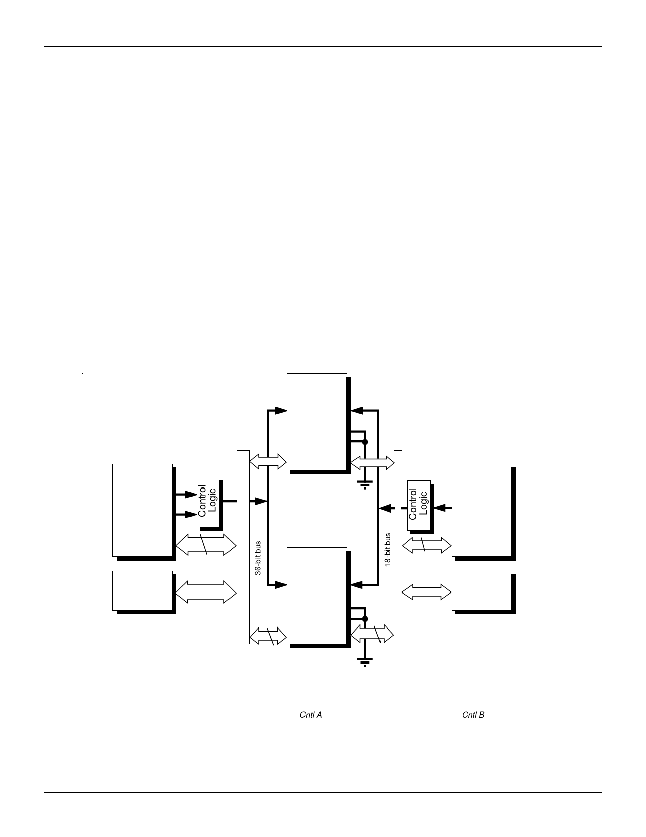
36-BIT PROCESSOR to 18-BIT PROCESSOR CONFIGURATION
Processor
A
Address
Control
IDT
BiFIFO
(Stand-Alone)
Cntl A Cntl B
ACK
REQ
CLK
Data A Data B
Processor
B
Control
Data
36
RAM
IDT
BiFIFO
(Stand-Alone)
Cntl A Cntl B
ACK
REQ
CLK
Data A Data B
18
9
Data
18
RAM
2669 drw 04
Figure 1. 36- to 18-Bit Processor Interface Configuration
NOTE:
1. Upper BiFIFO only is used in 18- to 9-bit configuration. Note that Cntl A refers to CSA, A1, A0, R/WA and DSA; Cntl B refers to R/WB and DSB or RB
and WB.
5.31
6
Share Link: