IDT72510L25J 데이터 시트보기 (PDF) - Integrated Device Technology
부품명
상세내역
일치하는 목록
IDT72510L25J
Integrated Device Technology

IDT72510L25J Datasheet PDF : 32 Pages
| |||
IDT72510, IDT72520
BUS MATCHING BIDIRECTIONAL FIFO
COMMERCIAL TEMPERATURE RANGE
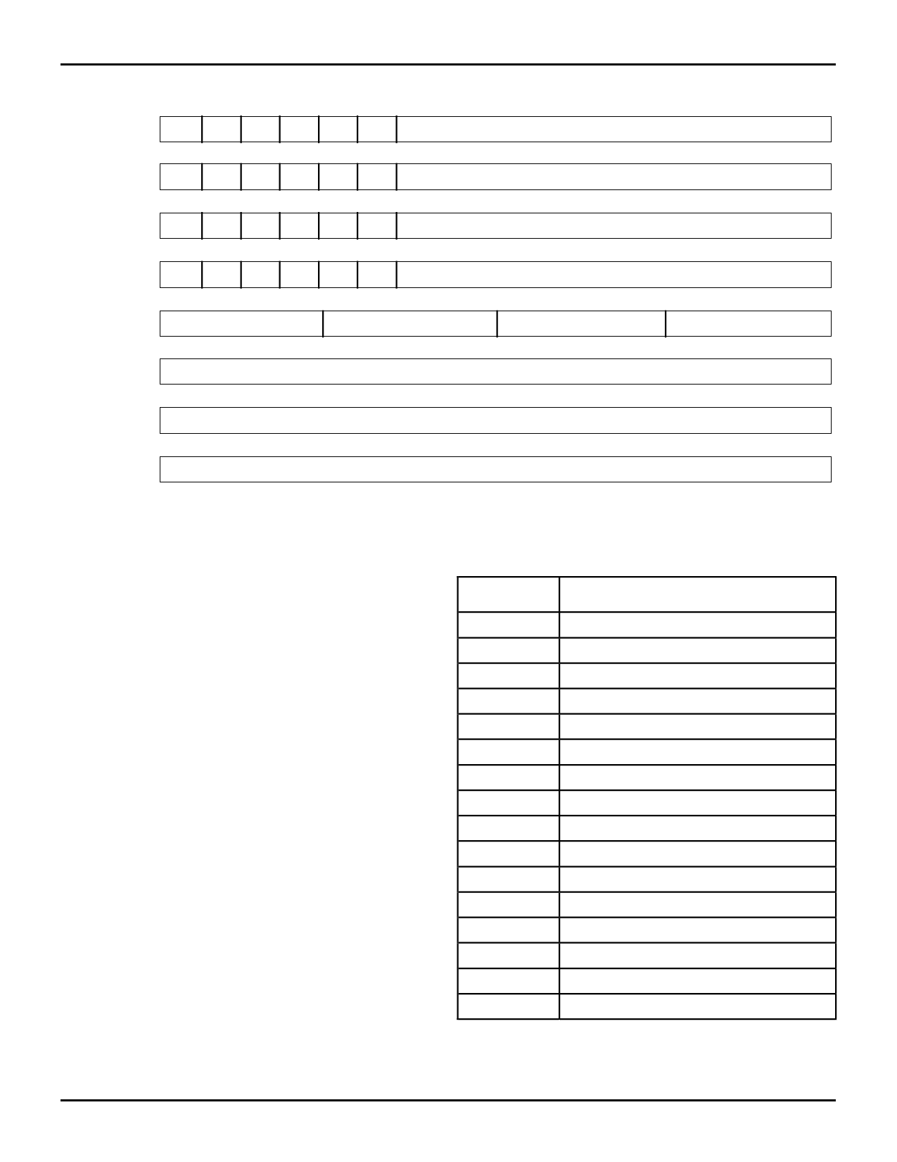
CONFIGURATION REGISTER FORMATS
15
10 9
Config. Reg. 0 X X X X X X
0
A→B FIFO Almost-Empty Flag Offset
15
10 9
Config. Reg. 1 X X X X X X
0
A→B FIFO Almost-Full Flag Offset
15
10 9
Config. Reg. 2 X X X X X X
0
B→A FIFO Almost-Empty Flag Offset
15
10 9
0
Config. Reg. 3 X X X X X X
B→A FIFO Almost-Full Flag Offset
Config. Reg. 4
15
12
Flag D Pin Assignment
11
8
Flag C Pin Assignment
7
4
Flag B Pin Assignment
3
0
Flag A Pin Assignment
15
0
Config. Reg. 5
General Control
15
0
Config. Reg. 6
Reserved
15
0
Config. Reg. 7
Parity Control
NOTE:
1. Bit 9 of Configuration Registers 0-3 must be set to 0 on the IDT72510.
Table 9. The BiFIFO Configuration Register Formats
2669 tbl 13
checking is enabled for data read and written through Port B.
Bit 8 controls parity checking and generation for B→A write data.
Bit 9 controls parity checking and generation for A→B read data.
Bit 10 controls whether the parity is odd or even. Bit 11 is used
to assign the internal parity checking error to the FLGA pin.
When the parity error is assigned to FLGA, the Configuration
Register 4 flag assignment for FLGA is ignored.
Programmable Flags
The IDT BiFIFO has eight internal flags; four of these flags
have programmable offsets, the other four are empty or full.
Associated with each FIFO memory array are four internal
flags, Empty, Almost-Empty, Almost-Full and Full, for the total
of eight internal flags. The Almost-Empty and Almost-Full
offsets can be set to any depth through the Configuration
Registers 0-3 (see Table 9). The offset (or depth) of FIFO RAM
array is based on the unit of an 18-bit word. The flags are
asserted at the depths shown in Table 13. After a hardware
reset or a software reset all, the almost flag offsets are set to
0. Even though the offsets are equivalent, the Empty and
Almost-Empty flags have different timing which means that
the flags are not coincident. Similarly, the Full and Almost-Full
flags are not coincident because of timing.
These eight internal flags can be assigned to any of four
external flag pins (FLGA-FLGD) through Configuration Reg-
ister 4 (see Table 10). For the specific flag timings, see
Figures 20-23.
The current state of all eight flags is available in the Status
Register in Status Register format 1. In Status Register format
0, only four flags can be found in the Status Register (see
Table 8).
EXTERNAL FLAG ASSIGNMENT CODES
Assignment
Code
0000
0001
0010
0011
0100
0101
0110
0111
Internal Flag Assigned to Flag Pin
A→B Empty
A→B Almost-Empty
A→B Full
A→B Almost-Full
B→A Empty
B→A Almost-Empty
B→A Full
B→A Almost-Full
1000
A→B Empty
1001
A→B Almost-Empty
1010
A→B Full
1011
A→B Almost-Full
1100
B→A Empty
1101
B→A Almost-Empty
1110
B→A Full
1111
B→A Almost-Full
2669 tbl 14
Table 10. Configuration Register 4 Internal Flag Assignments to
External Flag Pins.
5.31
13
Share Link: