CS5111 데이터 시트보기 (PDF) - Cherry semiconductor
부품명
상세내역
일치하는 목록
CS5111
Cherry semiconductor

CS5111 Datasheet PDF : 10 Pages
| |||
PACKAGE LEAD #
24 Lead SO Wide
1
2, 3
4
5,6,7,8,17,18,19,20
9
10
11
12
13
14
15
16
21
22
23
24
Package Lead Description
LEAD SYMBOL
FUNCTION
VIN
NC
VSW
Gnd
VFB1
VFB2
SELECT
COMP
COSC
WDI
CDelay
RESET
IBIAS
VLIN
VREG
ENABLE
Supply Voltage.
No connection.
Collector of NPN power switch for switching regulator section.
Connected to the heat removing leads.
Feedback input voltage 1 (referenced to 1.25V)
Feedback input voltage 2 (referenced to 1.25V)
Logic level input that selects either VFB1 or VFB2. An open selects
VFB2. Connect to Gnd to select VFB1.
Output of the transconductance error amplifier.
A capacitor connected to Gnd sets the switching frequency.
Refer to Figure 1d.
Watchdog input. Active on falling edge.
A capacitor connected to Gnd sets the Power On Reset and
Watchdog time.
RESET output. Active low if VLIN is below the regulation limit.
If watchdog timeout is reached, a reset pulse train is issued.
A resistor connected to Gnd sets internal bias currents as well as
the COSC and CDelay charge currents.
Regulated 5V output from the linear regulator section.
Input voltage to the linear regulator and the internal supply cir-
cuitry.
Logic level input to shut down the switching regulator.
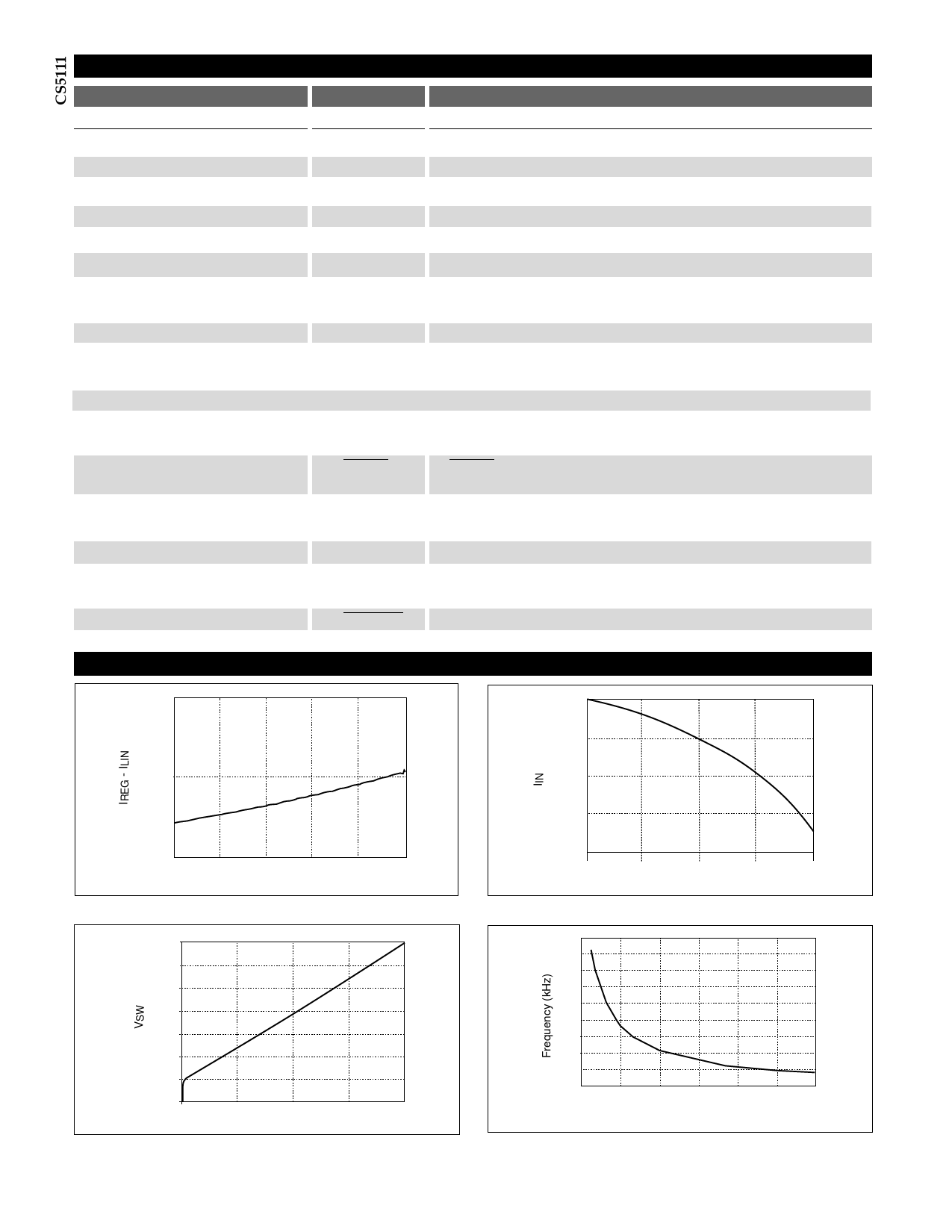
Typical Performance Characteristics
4.5mA
0A
4.0mA
-10mA
-20mA
3.5mA
0A
20mA 40mA
60mA 80mA
ILIN
Figure 1a. 5V Regulator Bias Current vs. Load Current.
100mA
1.4V
1.2V
1.0V
0.8V
0.6V
0.4V
0.2V
0.0V
0A
0.5A
1.0A
ISW
1.5A
2.0A
Figure 1c. Switch Saturation Voltage.
-30mA
-40mA
0A
0.5A
1.0A
ISW
1.5A
2.0A
Figure 1b. Supply Current vs. Switch Current.
180
160
140
120
100
80
60
40
20
0
0
500 1000 1500 2000 2500 3000
COSC (pF)
Figure 1d. Oscillator Frequency (kHz) vs. COSC (pF), assuming RBIAS =
64.9kΩ.
4
Share Link: