7641 데이터 시트보기 (PDF) - Mitsumi
부품명
상세내역
일치하는 목록
7641 Datasheet PDF : 149 Pages
| |||
PRELIMINARY NSocothimcaene:gpTeah.riasmisetnrioct laimfiintsalasrepescuibfijceacttioton.
MITSUBISHI MICROCOMPUTERS
7641 Group
SINGLE-CHIP 8-BIT CMOS MICROCOMPUTER
INTERRUPTS
There are twenty-four interrupt sources: five externals, eighteen
internals, and one software.
Interrupt Control
Each interrupt except the BRK instruction interrupt has both an Inter-
rupt Request Bit and an Interrupt Enable Bit, and is controlled by the
Interrupt Disable Flag (I). An interrupt occurs if the corresponding
Interrupt Request and Enable Bits are “1” and the Interrupt Disable
Flag is “0”.
Interrupt Enable Bits can be set or cleared by software. Interrupt Re-
quest Bits can be cleared by software, but cannot be set by software.
Additionally, an active edge of INT1 and INT2 can be selected by
using the interrupt edge select register (address 001116); an active
edge of CNTR0 can be done by using the timer X mode register
(address 002716); an active edge of CNTR1 can be done by using
the timer Y mode register (address 002816).
The BRK instruction interrupt and reset cannot be disabled with any
flag or bit. The I Flag disables all interrupts except the BRK instruc-
tion interrupt and reset. If several interrupts requests occur at the
same time, the interrupt with the highest priority is accepted first.
Interrupt Operation
When an interrupt request occurs, the following operations are auto-
matically performed:
1. The processing being executed is stopped.
2. The contents of the program counter and processor status reg-
ister are automatically pushed onto the stack.
3. The Interrupt Disable Flag is set and the corresponding in-
terrupt request bit is cleared.
4. The interrupt jump destination address is read from the vector
table into the program counter.
sNotes
When setting the followings, the interrupt request bit may be set to
“1”.
•When setting external interrupt active edge
Related register: Interrupt polarity select register (address 001116)
Timer X mode register (address 002716)
Timer Y mode register (address 002816)
When not requiring for the interrupt occurrence synchronized with
these setting, take the following sequence.
➀Set the corresponding Interrupt Enable Bit to “0” (disabled).
➁Set the Interrupt Edge Select Bit (Active Edge Switch Bit).
➂Set the corresponding Interrupt Request Bit to “0” after 1 or more
instructions have been executed.
➃Set the corresponding Interrupt Enable Bit to “1” (enabled).
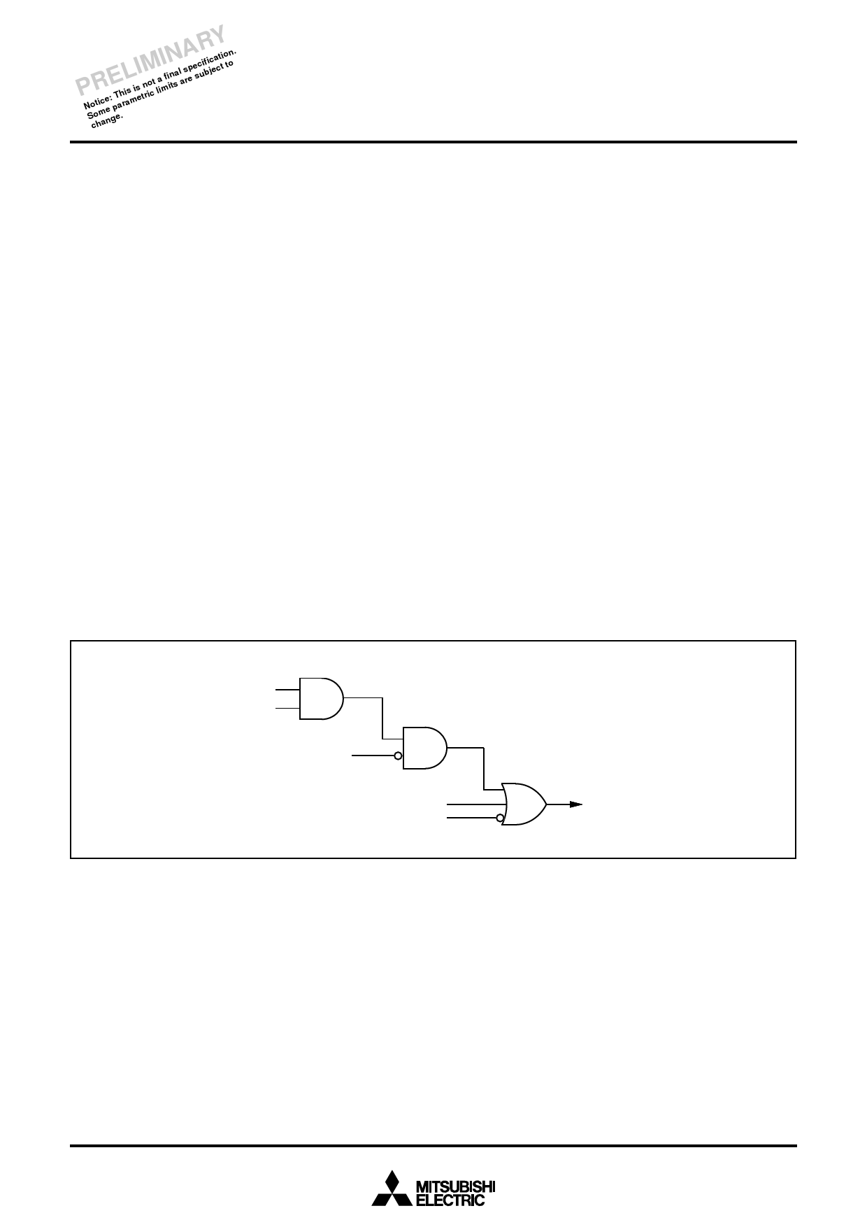
Interrupt request bit
Interrupt enable bit
Interrupt disable flag (I)
BRK instruction
Reset
Fig. 16 Interrupt control
Interrupt request
20
Share Link: 