M37640E8FP 데이터 시트보기 (PDF) - Mitsumi
부품명
상세내역
일치하는 목록
M37640E8FP Datasheet PDF : 96 Pages
| |||
Ver 1.4
MITSUBISHI MICROCOMPUTERS
7640 Group
SINGLE-CHIP 8-BIT CMOS MICROCOMPUTER
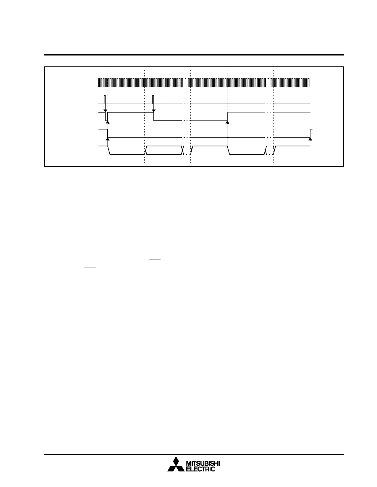
UxBRG
Clock
UxTRB1
Write
TBE
TCM
UTXDx
Start bit
D0
Stop bit
Start bit
Stop bit
Fig. 1.45. UART Transmit Operation Waveform
1.19.4.2 Receive Method
Set up
•Define the baud rate by writing a value from 0-255 into
UxBRG.
•Set the Receive Initialization Bit (RIN, bit 3 in the
UxCON), to "1".
•Configure the data format and the clock selection by
writing the appropriate value to UxMOD.
•Set the Request-To-Send Enable Bit (RTS_SEL, bit 6
of UxCON), if RTS handshaking will be used.
•Set the Receive Enable Bit (REN, bit 1 in the
UxCON), to "1".
Operation
•When a falling edge is detected on the URXDx pin,
the value on the pin is sampled at the basic clock rate,
which is 16 times faster than the baud rate. If the pin is
low for at least two cycles of the basic clock, the start
bit is detected. Sampling is again performed three
times in the approximate middle of the start bit. If two
or more of the samples are low, the start bit is deemed
valid. If two or more of the samples are not low, the
start bit is invalidated and the UART again begins wait-
ing for a falling edge on the URXDx pin.
•Once a valid start bit has been detected, input data re-
ceived through the URXDx pin is read one bit at a time,
LSB first, into the receive shift register. As is the case
with the start bit, three samples are taken in the ap-
proximate middle of each data bit, the parity bit, and
the stop bit(s). If two or more of the samples are low, a
"0" is latched, and if two or more of the samples are
high, a "0" is latched.
•When the number of bits specified by the data format
has been received and the last stop bit is detected, the
contents of the receive shift register are transferred to
the receive buffer and the Receive Buffer Full Flag in
the UxSTS is set to a "1", if a receive error has not oc-
curred (see Figure 1.46). The RBF interrupt request is
also generated at this time if a receive error has not oc-
curred. However, if a receive error did occur, the
appropriate error flags are set and the Receive Error
Sum (SER) interrupt request is generated at this time.
•When the low-order byte of the receive buffer
(UxTRB1) is read, the Receive Buffer Full Flag is
cleared, and the receive buffer is now ready for the next
byte. If 9-bit character length has been selected, the
high-order byte of the receive buffer (UxTRB2) should
be read before reading the low-order byte (UxTRB1).
45
Share Link: 