GF9105A 데이터 시트보기 (PDF) - Unspecified
부품명
상세내역
일치하는 목록
GF9105A Datasheet PDF : 37 Pages
| |||
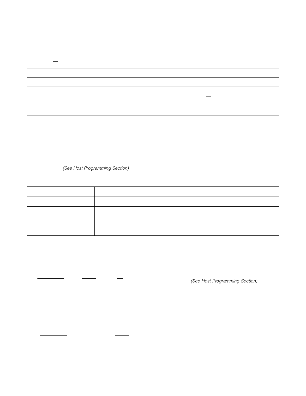
MATRIX OUTPUT RESOLUTION
Full precision is maintained within the 3X3 matrix multiplier until the output is rounded to a 13-bit or 11-bit word, depending on
the state of the RND8/10 control bit.
3X3 MATRIX MULITPLIER OUTPUT RESOLUTION FOR Y/G, CB/B AND CR/R CHANNELS
RND8/10
DESCRIPTION
0
Matrix output channels rounded to 13 bits.
1
Matrix output channels rounded to 11 bits.
Output from the KEY scaler is also rounded and clipped based on the state of the RND8/10 control bit.
KEY SCALER OUTPUT
RND8/10
0
Output of KEY Scaler rounded to 11 bits.
1
Output of KEY Scaler rounded to 9 bits.
DESCRIPTION
OUTPUT OFFSET ADJUSTMENT
Output offset adjustment is provided to allow a specified set of offsets to be added to the data streams. The control bits
OOA1 and OOA0 (See Host Programming Section) determine which set of offsets is applied to the data.
OOA1 AND OOA0 CONTROL BITS
OOA1
OOA0
DESCRIPTION
0
0
Offsets of 64, 512, 512 and 64 are added to the Y/G, CB/B, CR/R and KEY channels respectively.
0
1
Offsets of 64, 64, 64 and 64 are added to the Y/G, CB/B, CR/R and KEY channels respectively.
1
0
Offsets of 0, 0, 0 and 0 are added to the Y/G, CB/B, CR/R and KEY channels respectively.
1
1
Offsets of 0, 512, 512 and 0 are added to the Y/G, CB/B, CR/R and KEY channels respectively.
OUTPUT CLIPPING
In the output clipping block, the data is clipped to a specific number of bits. The CLP_D1 and CLP_D0 control bits (See Host
Programming Section) determine the clipping mode that will occur.
OUTPUT MULTIPLEXER
The MUXED_OUT, 4:4:4:4/4:2:2:4_OUT, SL/DL_OUT and HVF_OUT control bits (See Host Programming Section) determine
the output data format.
Dual Link (SL/DL_OUT = 0)
When MUXED_OUT and 4:4:4:4/4:2:2:4_OUT are both set low, the device will multiplex the three channels of Y/G, CB/B and
CR/R data into a single channel of 4:2:2 data as prescribed by SMPTE 125M. KEY information will be presented in a KEY:2:2
format where the CB/CR samples in the key channel are set to color blanking levels as outlined in ITU-R-601. This mode can
only be used when the output data has been rounded to 10-bit or 8-bit unsigned data. The 4:2:2 data stream is presented
on Processing Core output data port C5 and the KEY:2:2 data is presented on Processing Core output data port C8.
When MUXED_OUT is set low and 4:4:4:4/4:2:2:4_OUT is set high, the device will multiplex the four channels of Y/G, CB/B,
CR/R and KEY information into two streams of 4:2:2 and KEY:2:2 data as prescribed by SMPTE 125M. This mode can only be
used when the output data has been clipped to 10-bit or 8-bit unsigned data. The 4:2:2 data stream is presented on
Processing Core output data port C5 and the KEY:2:2 data is output on Processing Core output data port C8. Timing
Reference Signals (TRS) may be inserted into the output data streams with such TRS signals conforming to the EAV/SAV
15
521 - 88 - 03
Share Link: 