LLL317R71H103MD01K 데이터 시트보기 (PDF) - Unspecified
부품명
상세내역
일치하는 목록
LLL317R71H103MD01K Datasheet PDF : 296 Pages
| |||
!Note • Please read rating and !CAUTION (for storage, operating, rating, soldering, mounting and handling) in this catalog to prevent smoking and/or burning, etc.
• This catalog has only typical specifications. Therefore, please approve our product specifications or transact the approval sheet for product specifications before ordering.
C02E.pdf
Nov.27,2017
!Caution
Continued from the preceding page.
8. Assembly
1. Handling
If a board mounted with capacitors is held with one hand,
the board may bend. Firmly hold the edges of the board
with both hands when handling.
If a board mounted with capacitors is dropped, cracks
may occur in the capacitors.
Do not use dropped boards, as there is a possibility that
the quality of the capacitors may be impaired.
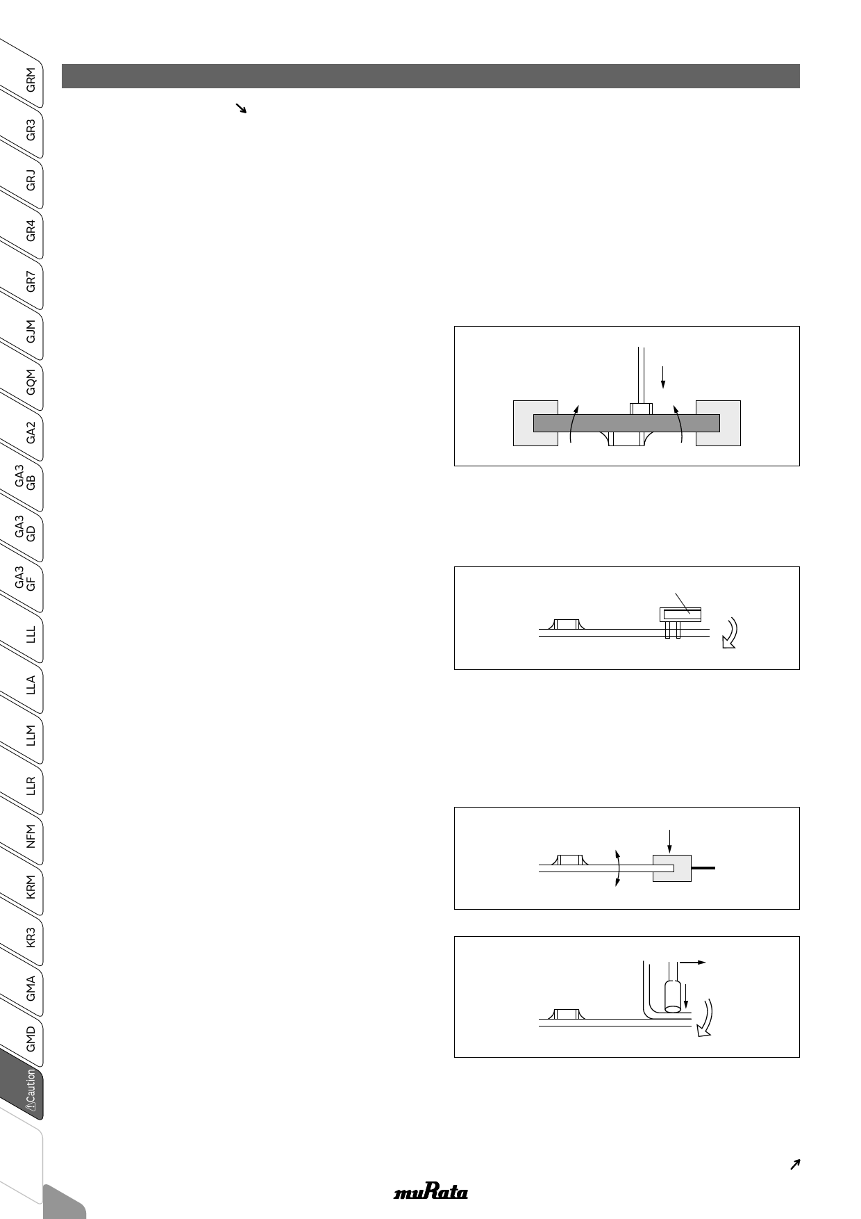
2. Attachment of Other Components
2-1. Mounting of Other Components
Pay attention to the following items, when mounting
other components on the back side of the board
a er capacitors have been mounted on the opposite
side.
When the bottom dead point of the suction nozzle is
set too low, board deflection stress may be applied
to the capacitors on the back side (bottom side), and
cracks may occur in the capacitors.
· A er the board is straightened, set the bottom
dead point of the nozzle on the upper surface of the
board.
· Periodically check and adjust the bottom dead point.
2-2. Inserting Components with Leads into Boards
When inserting components (transformers, IC, etc.)
into boards, bending the board may cause cracks in
the capacitors or cracks in the solder.
Pay attention to the following.
· Increase the size of the holes to insert the leads, to
reduce the stress on the board during insertion.
· Fix the board with support pins or a dedicated jig
before insertion.
· Support below the board so that the board does not
bend. When using support pins on the board,
periodically confirm that there is no di erence in
the height of each support pin.
2-3. Attaching/Removing Sockets and/or Connectors
Insertion and removal of sockets and connectors,
etc., might cause the board to bend. Please insure
that the board does not warp during insertion and
removal of sockets and connectors, etc., or the
bending may damage mounted components on the
board.
2-4. Tightening Screws
The board may be bent, when tightening screws, etc.
during the attachment of the board to a shield or
chassis.
Pay attention to the following items before
performing the work.
· Plan the work to prevent the board from bending.
· Use a torque screwdriver, to prevent
over-tightening of the screws.
· The board may bend a er mounting by reflow
soldering, etc. Please note, as stress may be applied
to the chips by forcibly flattening the board when
tightening the screws.
280
Suction Nozzle
Component with Leads
Socket
Screwdriver
Continued on the following page.
Share Link: 