LA7583 데이터 시트보기 (PDF) - SANYO -> Panasonic
부품명
상세내역
일치하는 목록
LA7583 Datasheet PDF : 16 Pages
| |||
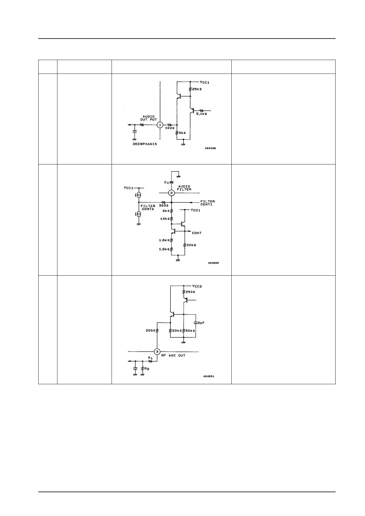
Pin Functions
Pin
No.
Symbol
1 FM DETECTOR
OUTPUT
2 FM AQT FILTER
3 RF AGC OUTPUT
LA7583
Circuit Configuration
GYLATOR
Description
Pin 1 is an audio FM output pin. A 100 Ω
resistor is connected in series with the
emitter follower.
(1) Monaural applications
CR are used to form a de-emphasis
cicuit externally.
t = CR1
(2) Audio multiplexing applications
Depending on the audio multiplexing
decoder application, the input
impedance is low, which may distort the
L-R signals, etc., and degrade the
stereo characteristics. In such an event,
add a resistor between pin 1 and GND.
R2 ^ 5.1 kΩ
Pin 2 is the FM Automatic Quadrature
Tuning filter pin. This pin controls the
quadrature detector so that it remains at its
center frequency (4.5 MHz), and is the point
where the two control currents are added.
If the value of external capacitor C1 is small,
the low-range frequency characteristics
deteriorate. If the capacitance is too large,
the low-range characteristics improve, but
the response characteristics at SW-ON, etc.,
worsen.
The recommended value for C1 is 10 µF to
33 µF.
Pin 3 is the RF AGC output pin. It is an
emitter output, and a protective resistor of
200 Ω is connected between pin 3 and
emitter.
This pin determines the resistance bleeder
(R1, R2) values according to the maximum
gain of the tuner.
Continued on next page.
No.5177-7/16
Share Link: 