LA7583 데이터 시트보기 (PDF) - SANYO -> Panasonic
부품명
상세내역
일치하는 목록
LA7583 Datasheet PDF : 16 Pages
| |||
LA7583
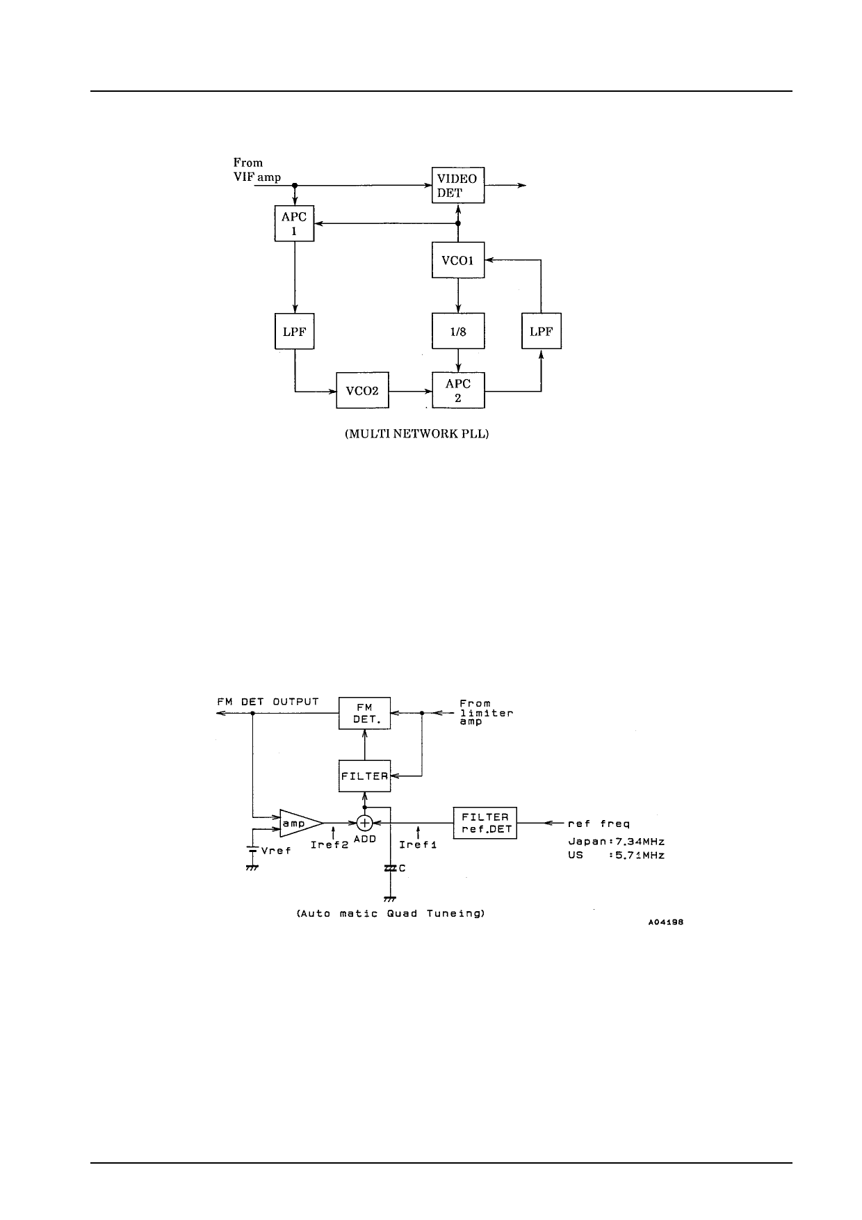
[Multinetwork PLL]
The multinetwork PLL consists of the blocks shown below.
The multinetwork PLL has two VCO circuits. Each of these form a separate PLL. The operational relationship between these
circuits is as follows:
fVCO1 = fVCO2 × 8
Initially, in APC1, the phases of the IF signal and the VCO carrier are compared. The control signal derived is then used to
control VCO2. VCO1 is controlled by comparing the phases of VCO2 and VCO1 x 1/8. As a result, VCO1 always has the same
frequency as the IF signal, and the following relationship results:
fVCO1 = fVCO2 × 8
If the precision of the ceramic oscillator for fVCO2 is within the adjustment range for VCO in a typical PLL, the video detector
phase error is very small. As a result, the multinetwork PLL operates as an ideal PLL detector.
Automatic Quadrature Tuning (AQT)
A quadrature detector that is controlled automatically is used in the FM detector. The AQT in the LA7583 consists of the blocks
shown in the following diagram.
The FM detection filter (gyrator) is controlled at 4.5 MHz by the control current (Iref1) generated by reference circuit 1. At the
same time, precision control is performed by using the control current (Iref2) derived by detecting the offset from the detected
output so that the FM detector phase relationship is 90 °. As a result, automatic control makes an ideal quadrature detector
possible.
(Note) Gyrator: Circuit-formed equivalent inductance
The SIF circuit contains a 4.5 MHz tank circuit having the gyrator and an internal capacitor.
No.5177-6/16
Share Link: 