NCP1560(2003) 데이터 시트보기 (PDF) - ON Semiconductor
부품명
상세내역
일치하는 목록
NCP1560 Datasheet PDF : 18 Pages
| |||
NCP1560
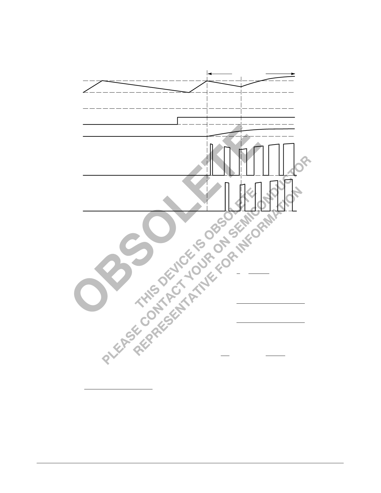
Once the UV or OV condition is removed and VAUX
reaches 11 V, the controller initiates a soft start cycle.
Figure 31 shows the relationship between the UV/OV
voltage, the outputs and the soft start voltage.
VAUX(on)
VAUX
VAUX(off)
0V
2V
0V
0V
UV/OV Voltage
Soft Start Voltage
The UV/OV pin can also be used to implement a remote
enable/disable function. Biasing the UV/OV pin below its
UV threshold disables the converter.
SOFT START
OUT2
0V
OUT1
0V
Figure 31. Soft Start Timing Diagram (Using Auxiliary Winding)
Feedforward Ramp Generator
The NCP1560 incorporates line feedforward (FF) to
compensate for changes in line voltage. A FF Ramp
proportional to Vin is generated and compared to VEA. If the
line voltage changes, the FF Ramp slope changes
accordingly. The duty cycle will be adjusted immediately
instead of waiting for the line voltage change to propagate
around the system and be reflected back on VEA.
A resistor between Vin and the FF pin (RFF) sets the
feedforward current (IFF). The FF Ramp is generated by
charging an internal 10 pF capacitor (CFF) with a constant
current proportional to IFF. The FF Ramp is finished
(capacitor is discharged) once the Oscillator Ramp reaches
2.0 V. Please refer to Figure 2 for a functional drawing of the
Feedforward Ramp generator.
IFF is usually a few hundred microamps, depending on the
operating frequency and the required duty cycle. If the
operating frequency and maximum duty cycle are known,
IFF is calculated using the equation below:
IFF
+
CFF
6.7
VDC(inv) 125
kW ton(max)
kW
where VDC(inv) is the voltage on the inverting input of the
Max DC Comparator and ton(max) is the maximum ON time.
Figure 18 shows the relationship between IFF and DCMAX.
For example, if a system is designed to operate at 300 kHz,
with a 60% maximum duty cycle at 36 V, the DCMAX pin can
be grounded and IFF is calculated as follows:
T
+
1
f
+
1
300 kHz
+
3.33
ms
ton(max) + DCMAX T + 0.6 3.33 ms + 2.0 ms
IFF
+
CFF
6.7
VDC(inv) 125
kW ton(max)
kW
+
10
pF
6.7
0.888
kW
V
2.0
125
ms
kW
+
82.8
mA
As the minimum line voltage is 36 V, the required
feedforward resistor is calculated using the equation below:
RFF
+
Vin
IFF
*
12.0
kW
+
36
82.8
V
mA
*
12.0
kW
[
434
kW
From the above calculations it can be observed that IFF is
controlled predominantly by the value of RFF, as the
resistance seen into the FF pin is only 12 kW. If a tight
maximum duty cycle control over temperature is required,
RFF should have a low thermal coefficient.
http://onsemi.com
14
Share Link: 