VP2612CGGPFR 데이터 시트보기 (PDF) - Mitel Networks
부품명
상세내역
일치하는 목록
VP2612CGGPFR Datasheet PDF : 11 Pages
| |||
VP2612
monitoring is, however, done by the FEC block as described
later.
The two address pointers can be read by the system
processor, thus allowing the level of the buffer to be monitored.
These are provided as 16 bit words with no truncation, and thus
require two bytes. The 16 bit value is internally frozen when the
most significant byte is requested by the system processor, and
for accuracy the write pointer should be read first. There is also
a control register bit which selects a buffer size of either 256kbits
or 512kbits.
FEC Block
The FEC section performs the framing, and adds the error
correction parity bits. If sufficient data for a frame is not available
in the transmission buffer, then the frame will be stuffed
automatically. There is no absolute threshold at which the FEC
will start to stuff, as the buffer level monitor in the FEC only works
to a resolution of ±128bits. FEC stuffing can also be forced by
setting the "Force FEC stuffing" bit in the VMUX/FEC control
register.
If the buffer level reaches a threshold, internally set to 512
short of the buffer being full, the OVERFLOW output is asserted.
DMODE3:0
FUNCTION
0000
0001
0010
0011
0100
0101
0110
0111
1000
1001
1010
1011
1100
1101
1110
1111
GOB Number
MB Number
Control Decisions
Quant Value
Horizontal MV
Vertical MV
Coded Blk Pattern
Sub-Block No.
Zero Run Count
RLC Coefficient
Not Used
Not Used
Not Used
Not Used
Not Used
Wait State
Table 1
This is to warn the system processor that drastic action is
needed to avert a buffer overflow, which will result in corruption
and loss of data. Since the buffer level monitor only works to
resolution of ±128bits, then the overflow detection can only be
accurate to ±128bits.
VP2611 Interface
The VMUX has been designed to interface directly to
the VP2611 encoder, with no buffering. The interface consists
of two buses DBUS7:0 and DMODE3:0, and a strobe signal
DCLK. The value on DMODE3:0 identifies the data type on
DBUS7:0 during the same period (see Table 1).
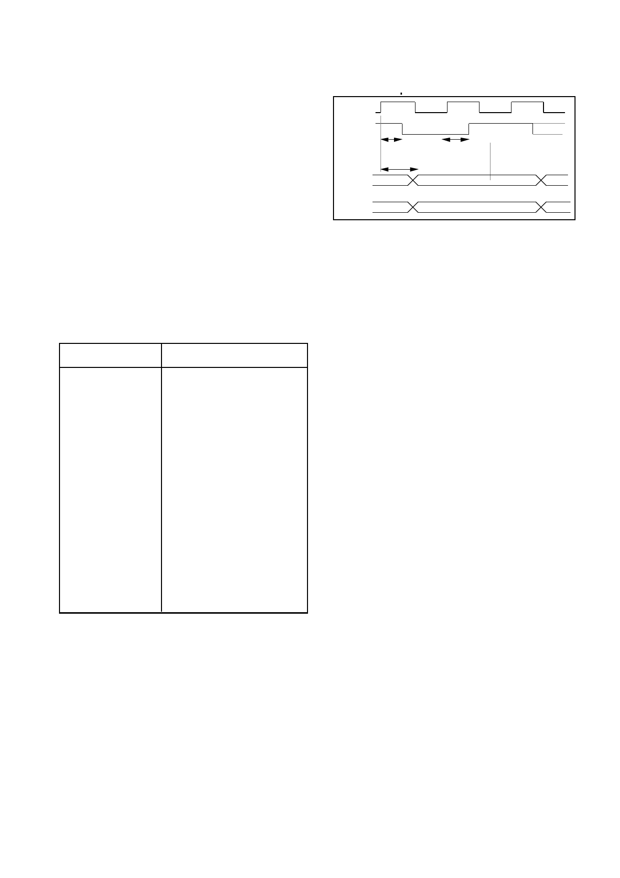
The output of the VP2611 is structured such that the
data on DBUS7:0 and DMODE3:0 is always valid for at
SCLK
DCLK
25ns max
25ns max
DATA FROM
VP2611
20ns max
DATA VALID
DMODE
3:0
DATA VALID
Figure 2. DBUS Timing
least two cycles, and DCLK is high for minimum of one
cycle. The rising DCLK edge occurs one cycle after
DBUS7:0 and DMODE3:0 are valid, as shown in Figure 2.
The sequence of events, and the duration of each
event, is shown in Figure 3. These duration times have
been chosen to satisfy the internal requirements of the
VP2612, and Wait States are inserted such that the time
to transfer a macroblock is always 2064 SCLK periods.
The parameters used by the VP2612 are described
in more detail below;
GOB Number : The current GOB Number is provided on
DBUS3:0 after the Control Decisions byte. (DBUS3 is
MSB).
MB Number : After the GOB Number, the macroblock
Number is provided on DBUS5:0 (DBUS5 is MSB).
Control Decisions : This byte shows which control decisions
have been taken for the forthcoming macroblock, and is
the first in the sequence. DBUS0 will be high if a Fixed
Macroblock (FIX MB) was enforced i.e. no new data will
be transmitted this macroblock. DBUS1 indicates
whether Inter (high) or Intra (low) coding was used for the
macroblock. DBUS2 will be high if the macroblock was
filtered, and DBUS3 will be high if motion compensation
was used. DBUS5 will be high if the current frame is being
coded in FAST UPDATE mode. In this mode the com-
plete frame will be intra coded. DBUS6 will be high if the
current frame is a SKIP FRAME i.e. not being coded - so
no coefficients will be transmitted. DBUS4 and DBUS7
are not used.
Quant Value :The quantisation value used in processing the
current macroblock is provided on DBUS4:0 (DBUS4 is
MSB). This represents an actual quantisation level be-
tween 2 and 62, in steps of 2 and as defined in H.261.
Horizontal MV : If motion compensation was used the hori-
zontal component of the motion vector will be provided on
DBUS4:0 (DBUS4 is MSB). (This 5 bit value represents
a two's complement number in the range (-15 to +15)
(although only vectors in the range +7/-8 are currently
possible with the VP2611). If motion compensation was
not used this is a don't care value.
3
Share Link: 