72605L20 데이터 시트보기 (PDF) - Integrated Device Technology
부품명
상세내역
일치하는 목록
72605L20 Datasheet PDF : 20 Pages
| |||
IDT72605/IDT72615 CMOS SyncBiFIFO
256 x 18 x 2 and 512 x 18 x 2
COMMERCIAL TEMPERATURE RANGE
CSA A2
A1
A0
Read
Write
0
0
0
0
B→A FIFO A→B FIFO
0
0
0
1
18-bit Bypass Path
0
1
0
0
A→B FIFO Almost-Empty
Flag Offset
0
1
0
1
A→B FIFO Almost-Full
Flag Offset
0
1
1
0
B→A FIFO Almost-Empty
Flag Offset
0
1
1
1
B→A FIFO Almost-Full
Flag Offset
1
X
X
X
Port A Disabled
2704 tbl 10
Table 2. Accessing Port A Resources Using CSA, A2, A1, and A0.
PORT A CONTROL SIGNALS
The Port A control signals pins dictate the various opera-
tions shown in Table 2. Port A is accessed when CSA is LOW,
and is inactive if CSA is HIGH. R/WA and ENA lines determine
when Data A can be written or read. If R/WA and ENA are LOW,
data is written into input register on the LOW-to-HIGH transition
of CLKA. If R/WA is HIGH and OEA is LOW, data comes out
of bus and is read from output register into three-state buffer.
Refer to pin descriptions for more information.
PROGRAMMABLE FLAGS
The IDT SyncBiFIFO has eight flags: four flags for A→B FIFO
(EFAB, PAEAB, PAFAB, FFAB), and four flags for B→A FIFO
(EFBA, PAEBA, PAFBA, FFBA). The Empty and Full flags are
fixed, while the Almost Empty and Almost Full offsets can be
set to any depth through the Flag Offset Registers (see Table
3). The flags are asserted at the depths shown in the Flag
Truth Table (Table 4). After reset, the programmable flag
offsets are set to 8. This means the Almost Empty flags are
asserted at Empty +8 words deep, and the Almost Full flags
are asserted at Full -8 words deep.
The PAEAB is synchronized to CLKB, while PAEAB is syn-
chronized to CLKA; and PAEBA is synchronized to CLKA, while
PAEBA is synchronized to CLKB. If the minimum time (tSKEW2)
between a rising CLKB and a rising CLKA is met, the flag will
change state on the current clock; otherwise, the flag may not
change state until the next clock rising edge. For the specific
flag timings, refer to Figures 12-15.
PORT B CONTROL SIGNALS
The Port B control signal pins dictate the various operations
shown in Table 5. Port B is independent of CSA. R/WB and
ENB lines determine when Data can be written or read in Port
B. If R/WB and ENB are LOW, data is written into input register,
and on LOW-to-HIGH transition of CLKB data is written into
PAEAB Register
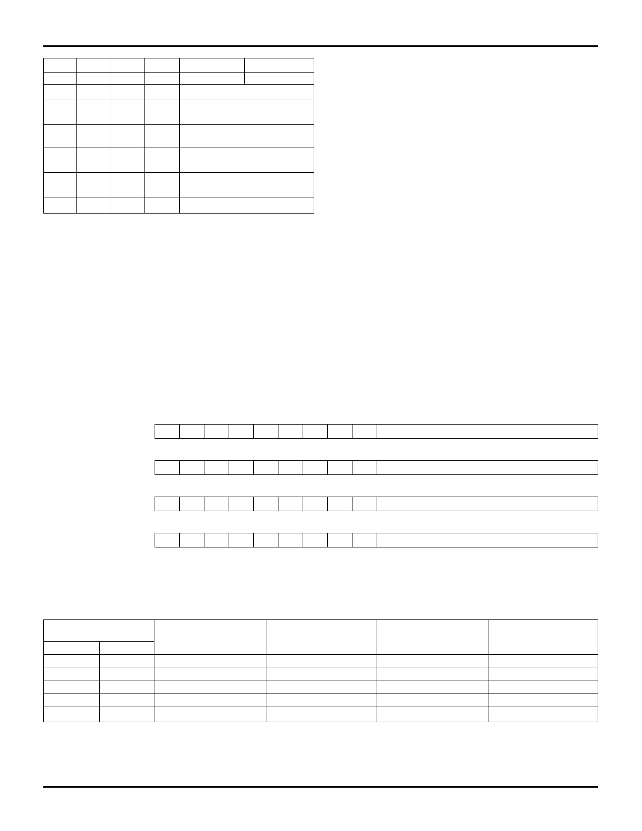
17 16 15 14 13 12 11 10 9 8 7 6 5 4 3 2 1 0
XXXXXXXXX
A→B FIFO Almost-Empty Flag Offset
PAFAB Register
17 16 15 14 13 12 11 10 9 8 7 6 5 4 3 2 1 0
XXXXXXXXX
A→B FIFO Almost-Full Flag Offset
PAEBA Register
17 16 15 14 13 12 11 10 9 8 7 6 5 4 3 2 1 0
XXXXXXXXX
B→A FIFO Almost-Empty Flag Offset
PAFBA Register
17 16 15 14 13 12 11 10 9 8
XXXXXXXXX
NOTE:
1. Bit 8 must be set to 0 for the IDT72605 (256 x 18) Synchronous BiFIFO.
Table 3. Flag Offset Register Format.
76543210
B→A FIFO Almost-Full Flag Offset
2704 tbl 11
Number of Words
in FIFO
From
To
0
0
1
n
n+1
D-(m+1)
D-m
D-1
D
D
EF
LOW
HIGH
HIGH
HIGH
HIGH
PAE
LOW
LOW
HIGH
HIGH
HIGH
NOTES:
n = Programmable Empty Offset (PAEAB Register or PAEBA Register)
m = Programmable Full Offset (PAFAB Register or PAFBA Register)
D = FIFO Depth (IDT72605 = 256 words, IDT72615= 512 words)
Table 4. Internal Flag Truth Table.
5.18
PAF
HIGH
HIGH
HIGH
LOW
LOW
FF
HIGH
HIGH
HIGH
HIGH
LOW
2704 tbl 12
9
Share Link: 