CDP1879 데이터 시트보기 (PDF) - Intersil
부품명
상세내역
일치하는 목록
CDP1879 Datasheet PDF : 18 Pages
| |||
CDP1879, CDP1879C-1
caler that supplies a once-a-second pulse to the counters. The
seconds counter divide the pulse by 60 and its output clocks
the minute counter every 60 seconds Further division by the
minutes, hours, day of month and month counters result in 5
counters holding data that reflect the time/calendar from sec-
onds to months. The counters are addressed separately and
BCD data is transferred to and from via the data bus. The most
significant bit of the hours counter (Bit 7) is user programmed to
indicate AM or PM and will be inverted every 12th hour. (0=AM,
1=PM). Bit 6 of the hours counter is user programmed to
enable the hours counter for 12 or 24 hour operation.
(0=24,1=12). If 24-hour operation is selected, the AM-PM bit is
“don't care”, but still toggles every 12th hour. Writing to the sec-
onds counter resets the last 7 stages of the prescaler, allowing
time accuracy to approximately 1/100 of a second.
FREEZE
CIRCUIT
AM - PM
AND
HOUR LOGIC
CALENDAR
LOGIC
XTAL
OSCILLATOR
XTAL
PRESCALE
SECOND
MINUTE
HOUR
DAY
MONTH
PRESCALE CLOCK
SELECT SELECT
CLOCK OUT
INT
RESET
VDD
VSS
CLOCK AND
INT. LOGIC
CONTROL
REGISTER
INT. STATUS
REGISTER
8-BIT DATA BUS
COMPARATOR
SECOND
LATCH
MINUTE
LATCH
HOUR
LATCH
I/O
INTERFACE
DB0-DB7
A0
A1
A2
TPA
IO/MEM
TPB/WR
RD
CS
POWER DOWN
ADDRESS DECODE
AND
CONTROL LOGIC
FIGURE 4. FUNCTIONAL DIAGRAM - CONTROL REGISTER HIGHLIGHTED
The most significant bit of the month counter is a Leap Year
bit. If it is set to “1”, the counter will count to February 29,
then roll to March 1. If set to “0” it will go to March 1st after
February 28th.
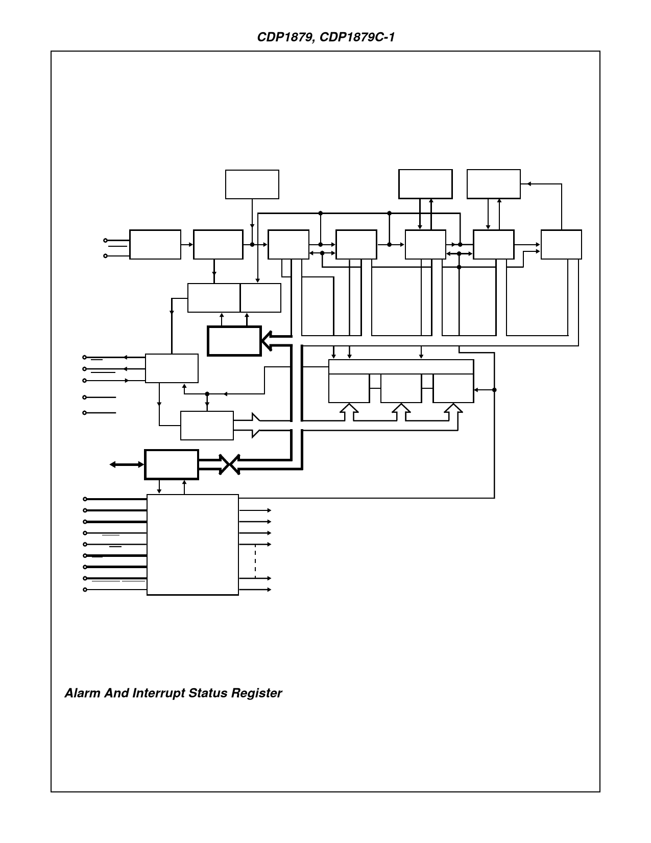
Alarm And Interrupt Status Register
The alarm circuit consists of 1) seconds, minutes and hour
alarm latches that hold the alarm time, 2) the outputs of the
seconds, minutes and hour counters, and 3) a comparator
that drives an interrupt output. The comparator senses the
counter and alarm latch values and activates the interrupt
output (active low) when they are equal (see Figure 3).
The write-only alarm latches have the same addresses as
their comparable counters. Bit 3 in the control register deter-
mines data direction to the latches or counters and alarm
enabling. For example, during a write cycle, if bit-3 in the
control register is a “1”, addressing the seconds counter or
alarm latch will load the seconds alarm latch from the data
bus and will enable the alarm function. Conversely, if bit-3 in
the control register is a “0”, addressing the seconds counter
or alarm latch during a write cycle will place the value on the
data bus into the seconds counter and will disable the alarm
function. The interrupt output can be activated by the alarm
circuit or the clock output. When an interrupt occurs, the
4-112
Share Link: 