NCP693 데이터 시트보기 (PDF) - ON Semiconductor
부품명
상세내역
일치하는 목록
NCP693 Datasheet PDF : 13 Pages
| |||
NCP693
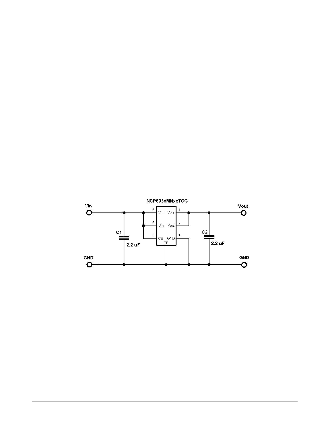
APPLICATIONS INFORMATION
A typical application circuit for the NCP693 series is
shown in Figure 2.
Input Decoupling (C1)
A 2.2 mF capacitor either ceramic or tantalum is
recommended and should be connected as close as possible
to the pins of NCP693 device. Higher values and lower ESR
will improve the overall line transient response.
Output Decoupling (C2)
The minimum decoupling value is 2.2 mF and can be
augmented to fulfill stringent load transient requirements.
The regulator accepts ceramic chip capacitors as well as
tantalum devices. If a tantalum capacitor is used, and its ESR
is large, the loop oscillation may result. Because of this,
select C2 carefully considering its frequency characteristics.
Larger values improve noise rejection and load regulation
transient response.
Enable Operation
The enable pin CE will turn on or off the regulator. These
limits of threshold are covered in the electrical specification
section of this data sheet. If the enable is not used then the
pin should be connected to Vin. The D version devices
(NCP693DMNxxTCG) have additional circuitry in order to
reach the turn−off speed faster than normal type. When the
mode is into standby with CE signal, auto discharge
transistor turns on.
Hints
Please be sure the Vin and GND lines are sufficiently wide.
If their impedance is high, noise pickup or unstable
operation may result.
Set external components, especially the output capacitor,
as close as possible to the circuit, and make leads as short as
possible.
Thermal
As power across the NCP693 increases, it might become
necessary to provide some thermal relief. The maximum
power dissipation supported by the device is dependent
upon board design and layout. Mounting pad configuration
on the PCB, the board material, and also the ambient
temperature effect the rate of temperature rise for the part.
This is stating that when the NCP693 has good thermal
conductivity through the PCB, the junction temperature will
be relatively low with high power dissipation applications.
Figure 2. Typical Application Circuit
http://onsemi.com
4
Share Link: 