MAX1980 데이터 시트보기 (PDF) - Maxim Integrated
부품명
상세내역
일치하는 목록
MAX1980
Maxim Integrated

MAX1980 Datasheet PDF : 33 Pages
| |||
Quick-PWM Slave Controller with
Driver Disable for Multiphase DC-DC Converter
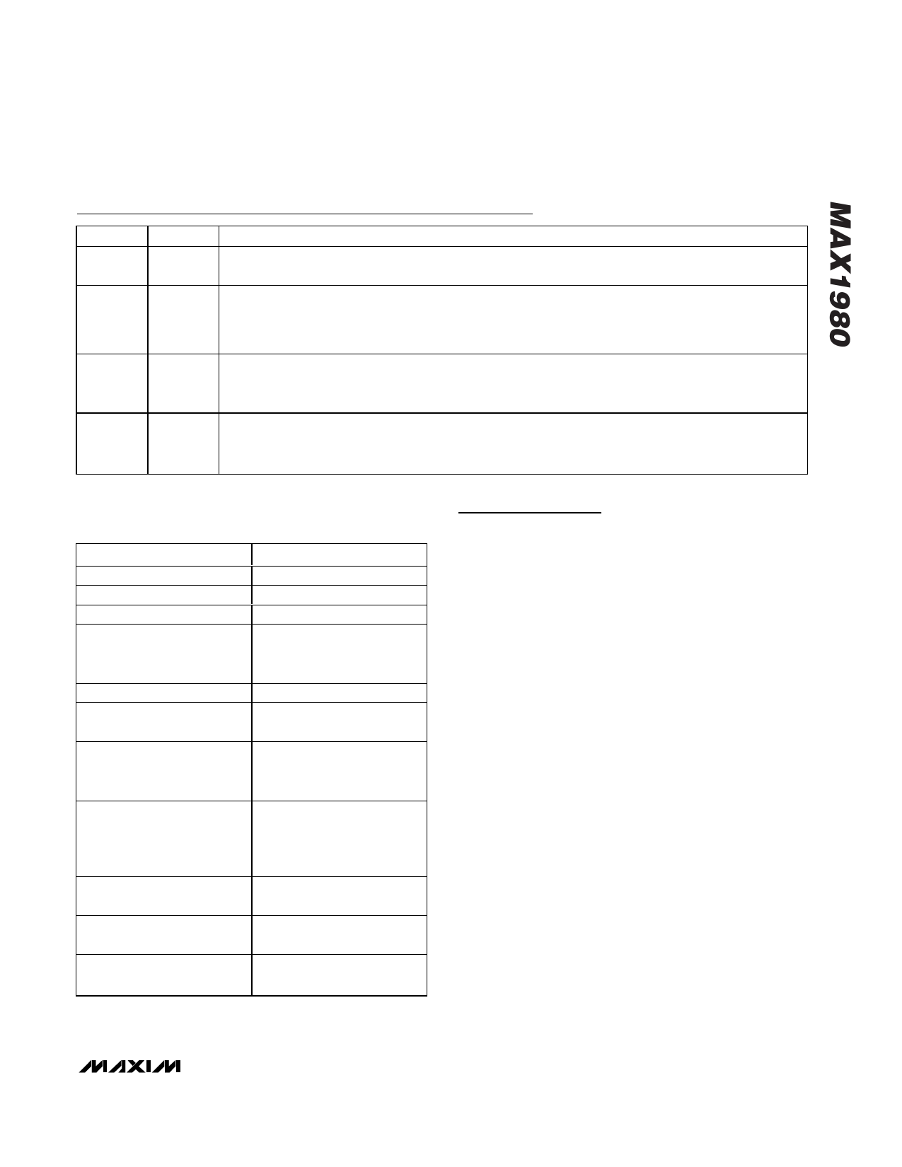
Pin Description (continued)
PIN
NAME
DESCRIPTION
17
V+
Battery Voltage Sense Connection. Connect V+ to the input power source. V+ is used only for PWM one-
shot timing (see the On-Time Control and Active Current Balancing section).
Open-Drain Current-Limit Output. Connect to the master controller’s adjustable current-limit input (ILIM)
18
LIMIT
according to the Standard Application Circuit (Figure 1). When the voltage across the master controller’s
current-sense resistor (VCM+ - VCM-) exceeds the current-limit threshold (VILIM/10), the MAX1980 pulls
LIMIT low.
Dual-Mode Current-Limit Adjustment and Standby Input. The current-limit threshold voltage is 1/10 the
19
ILIM
voltage seen at ILIM (VILIM) over a 400mV to 1.5V range. If VILIM drops below 250mV, the slave
controller enters a low-power standby mode, forcing DL low and DH low.
Trigger Input. Connect to the master controller’s low-side gate driver. The trigger input’s polarity is pin
20
TRIG selectable: POL = VCC or floating triggers on the rising edge (out-of-phase operation), and POL = GND
triggers on the falling edge (in-phase operation).
Table 1. Component Selection for Standard
Applications
COMPONENT
Output Voltage
Input Voltage Range
Maximum Load Current
Inductor (each phase)
Frequency
High-Side MOSFET
(NH, each phase)
Low-Side MOSFET
(NL, each phase)
Input Capacitor (CIN)
Output Capacitor (COUT)
Current-Sense Resistors
(RCS and RCM)
Voltage Positioning Gain
(AVPS)
CIRCUIT OF FIGURE 1
0.6V to 1.75V
7V to 24V
40A
0.6µH
Sumida CDEP134H-0R6 or
Panasonic ETQP6F0R6BFA
300kHz (TON = float)
International Rectifier
(2) IRF7811W
International Rectifier
(2) IRF7822 or
Fairchild (3) FDS7764A or
(6) 10µF, 25V
Taiyo Yuden
TMK432BJ106KM or
TDK C4532X5R1E106M
(8) 270µF, 2.0V
Panasonic EEFUE0E271R
1.5mΩ
1
Detailed Description
The MAX1980 step-down slave controller is intended for
low-voltage, high-current, multiphase DC-DC applica-
tions. The MAX1980 slave controller can be combined
with any of Maxim’s Quick-PWM step-down controllers to
form a multiphase DC-DC converter. When compared to
single-phase operation, multiphase conversion lowers the
peak inductor current by distributing the load current
between parallel power paths. This simplifies component
selection, power distribution to the load, and thermal lay-
out. Existing Quick-PWM controllers, such as the
MAX1718, function as the master controller, providing
accurate output-voltage regulation, fast transient
response, and multiple fault-protection features.
Synchronized to the master’s low-side gate driver, the
MAX1980 includes a constant on-time controller, syn-
chronous rectifier gate drive, active current balancing,
and precision current-limit circuitry.
On-Time Control and Active
Current Balancing
The MAX1980 slave controller uses a constant on-time,
voltage feed-forward architecture similar to Maxim’s
Quick-PWM controllers (Figure 2). The control algorithm
is simple: the high-side switch on-time is determined
solely by a one-shot whose period is inversely propor-
tional to input voltage and directly proportional to the
compensation voltage (VCOMP). Another one-shot sets a
minimum off-time (130ns typical). The on-time one-shot
is triggered when the following conditions are satisfied:
The slave detects a transition on the TRIG input, the
slave controller’s inductor current is below its current-
limit threshold, and the minimum off time has expired.
______________________________________________________________________________________ 11
Share Link: