M37640E8FP 데이터 시트보기 (PDF) - Mitsumi
부품명
상세내역
일치하는 목록
M37640E8FP Datasheet PDF : 96 Pages
| |||
Ver 1.4
MITSUBISHI MICROCOMPUTERS
7640 Group
SINGLE-CHIP 8-BIT CMOS MICROCOMPUTER
1.17 TIMERS
This device has five built-in timers: Timer X, Timer Y,
Timer 1, Timer 2, and Timer 3.
The contents of the timer latch, corresponding to
each timer, determine the divide ratio. The timers can
be read or written at any time. However, the read and
write operations on the high and low-order bytes of
the 16-bit timers (Timer X and Y) must be performed
in a specific order.
The timers are all down count timers; when the count
of a timer reaches 0016 (000016 for Timer X and Y),
an underflow occurs at the next count pulse and the
contents of the corresponding timer reload latch are
reloaded into the timer. When a timer underflows, the
interrupt request bit corresponding to that timer is set
to a “1”.
The divide ratio of a timer is given by 1/(n + 1), where
n is the value written to the timer. When the STP in-
struction is executed or RESET is asserted, 0116 is
loaded into Timer 2 and the Timer 2 reload latch, and
FF16 is loaded into Timer 1 and the Timer 1 reload
latch.
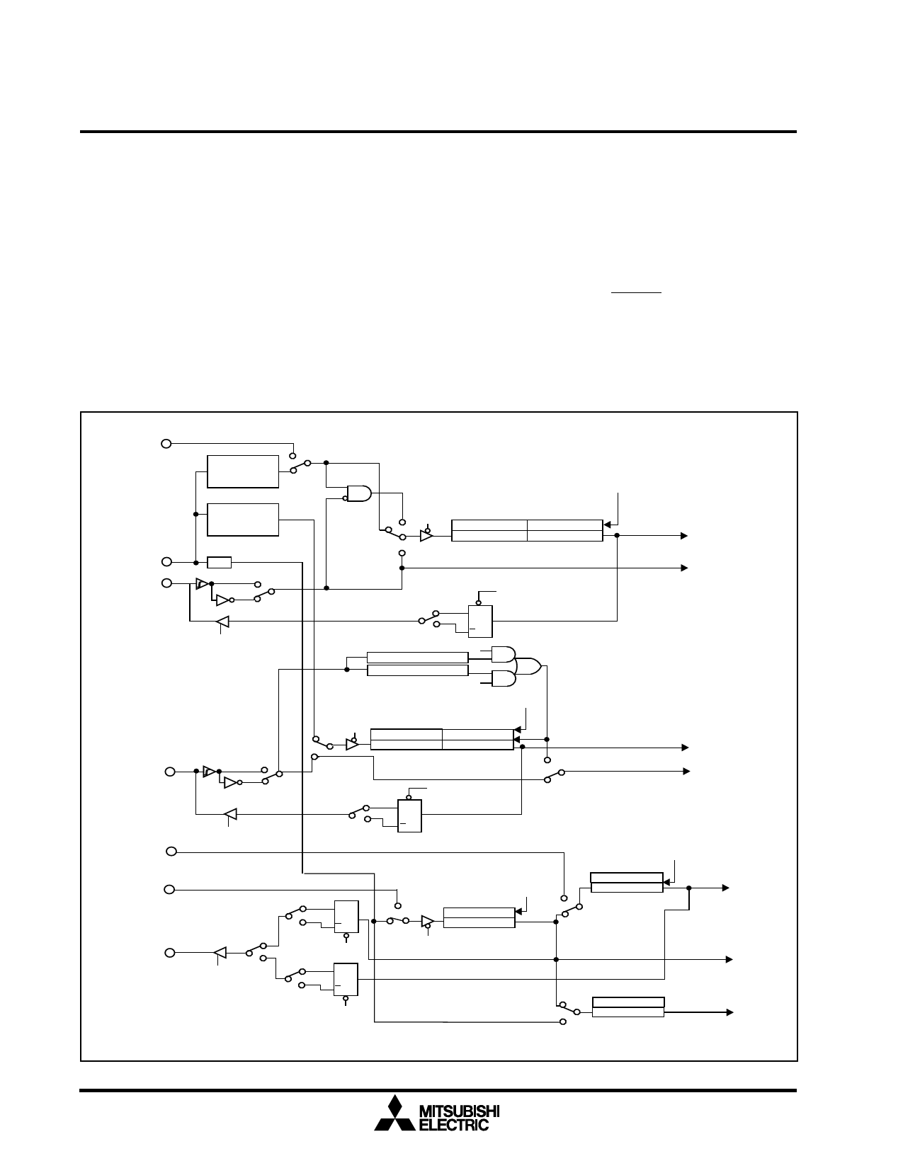
Figure 1.32 is a block diagram of the five timers.
SCSGCLK
TXM2,1
Timer X Divider
(1/n)
n=8, 16, 32, 64
1 TXM3
0
TXM5,4
TXM0
TYM3,2
Timer Y Divider
(1/n)
Φ
1/8
CNTR0
1
00 11 TXM7
01
Timer XL Latch(8) Timer XH Latch(8)
Timer XL (8)
Timer XH (8)
10
Timer X Interrupt Request
CNTR0 Interrupt Request
CNTR1
TXM6
0
TXM5, 4 = 01
1
TXM5,4= 01
TXM6 0
1
Q
T
Q
TYM5,4= 11
Rising Edge Detector
Falling Edge Detector
TYM5,4= 01
or
11
TYM0
TYM5,4
00
01
11
TYM7 Timer YL Latch(8)Timer YH Latch(8)
Timer YL (8) Timer YH (8)
11
10
TYM5,4
Timer Y Interrupt Request
TYM6
0
TYM= 1 & TYM5, 4 = 00
Φ
TYM6 0
1
00
TYM1= 11 and TYM5,4 = 0
01
QS
10
T
Q
CNTR1 Interrupt Request
T123M7
XCin/2
TOUT
T123M5 0
1
T123M0 0
1
0
T123M6= 1
T123M5 1
Q
T
QS
T123M6= 1
Q
T
QS
T123M6 =1
1 T123M2
T123M7
Timer 1 Latch(8)
Timer 1 (8)
0
T123M1
1
T123M3
0
0
T123M4
1
Timer 2 Latch(8)
Timer 2 (8)
Timer 2
Interrupt Request
Timer 1
Interrupt Request
Timer 3 Latch(8)
Timer3 (8)
Timer 3
Interrupt Request
Fig. 1.32. Block diagram of Timers X, Y, 1, 2, and 3
30
Share Link: 