CS8120YD14 데이터 시트보기 (PDF) - ON Semiconductor
부품명
상세내역
일치하는 목록
CS8120YD14 Datasheet PDF : 14 Pages
| |||
CS8120
functionally independent of the rest of the IC, thereby
guaranteeing that the RESET signal is valid for VOUT as low
as 1.0 V.
VOUT
CS8120
RESET
RRST
CRST
5.0 V to mP
and System
Power
C2
22 mF
to mP
RESET
Port
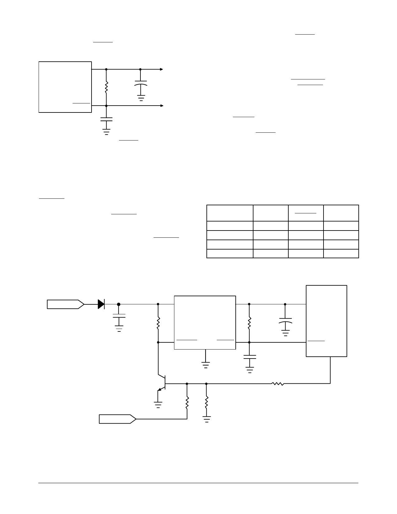
Figure 12. RC Network for RESET Delay Circuitry
An external RC network on the RESET lead (Figure 12)
provides a sufficiently long delay for most microprocessor
based applications. RC values can be chosen using the
following formula:
RTOT
ƪ ƫ ǒ Ǔ CRST +
−tDelay
ln
VT*VOUT
VRST*VOUT
where:
RTOT = RRST in parallel with RIN,
RIN = mP port impedance,
CRST = RESET delay capacitor,
tDelay = desired delay time,
VRST = VSAT of RESET lead (0.7 V @ turn − ON), and
VT = mP logic threshold voltage.
APPLICATION NOTES
The circuit depicted in Figure 13 lets the microprocessor
control its power source, the CS8120 regulator. An I/O port
on the mP and the SWITCH port are used to drive the base
of Q1. When Q1 is driven into saturation, the voltage on the
ENABLE lead falls below its lower threshold. The
regulator’s output is switched out. When the drive current is
removed, the voltage on the ENABLE lead rises, the output
is switched off and the IC moves into Sleep mode where it
draws 250 mA.
By coupling these two controls with the ENABLE, the
system has added flexibility. Once the system is running, the
state of the SWITCH is irrelevant as long as the I/O port
continues to drive Q1. The microprocessor can turn off its
own power by withdrawing drive current, once the
SWITCH is open. This software control at the I/O port
allows the microprocessor to finish key housekeeping
functions before power is removed.
The logic options are summarized in Table 1.
Table 1. Logic Control of CS8120 Output
Microprocessor
I/O Drive
SWITCH
ENABLE
Output
ON
Closed
LOW
ON
Open
LOW
ON
OFF
Closed
LOW
ON
Open
HIGH
OFF
The I/O port of the microprocessor typically provides
50 mA to Q1. In automotive applications the SWITCH is
connected to the ignition switch.
VBAT
C1
0.1 mF
500 kW
VIN
VOUT
CS8120
ENABLE GND RESET
RRST
CRST
VCC
C2
22mF
mP
RESET
I/O Port
SWITCH
Q1
500 kW
100 kW
100 kW
Figure 13. Microprocessor Control of CS8120 Using External Switching Transistor Q1
http://onsemi.com
7
Share Link: 