AD7641ASTRL 데이터 시트보기 (PDF) - Analog Devices
부품명
상세내역
일치하는 목록
AD7641ASTRL Datasheet PDF : 28 Pages
| |||
However, because the AD7641 has a fine lead pitch, guarding
this node is not practical. Therefore, in these industrial and
other types of applications, it is recommended to use a conformal
coating, such as Dow Corning® 1-2577 or HumiSeal® 1B73.
External 1.2 V Reference and Internal Buffer (PDBUF =
Low, PDREF = High)
To use an external reference along with the internal buffer,
PDREF should be high and PDBUF should be low. This powers
down the internal reference and allows the 1.2 V reference to
be applied to REFBUFIN, producing 2.048 V (typically) on
the REF pin.
External 2.5 V Reference (PDBUF = High, PDREF = High)
To use an external 2.5 V reference directly on the REF pin,
PDREF and PDBUF should both be high.
For improved drift performance, an external reference, such as
the AD780 or ADR431, can be used. The advantages of directly
using the external voltage reference are:
• The SNR and dynamic range improvement (about 1.7 dB)
resulting from the use of a reference voltage very close to
the supply (2.5 V) instead of a typical 2.048 V reference
when the internal reference is used. This is calculated by
SNR
=
20log⎜⎝⎛
2.048
2.50
⎟⎠⎞
• The power savings when the internal reference is powered
down (PDREF high).
PDREF and PDBUF power down the internal reference and
the internal reference buffer, respectively. The input current
of PDREF and PDBUF should never exceed 20 mA. This can
occur when the driving voltage is above AVDD (for instance, at
power-up). In this case, a 125 Ω series resistor is recommended.
Reference Decoupling
Whether using an internal or external reference, the AD7641
voltage reference input (REF) has a dynamic input impedance;
therefore, it should be driven by a low impedance source with
efficient decoupling between the REF and REFGND inputs.
This decoupling depends on the choice of the voltage reference
but usually consists of a low ESR capacitor connected to REF
and REFGND with minimum parasitic inductance. A 10 μF
(X5R, 1206 size) ceramic chip capacitor (or 47 μF tantalum
capacitor) is appropriate when using either the internal
reference or one of the recommended reference voltages.
The placement of the reference decoupling is also important to
the performance of the AD7641. The decoupling capacitor
should be mounted on the same side as the ADC right at the
REF pin with a thick PCB trace. The REFGND should also connect
to the reference decoupling capacitor with the shortest distance.
AD7641
For applications that use multiple AD7641 devices, it is more
effective to use an external reference with the internal reference
buffer to buffer the reference voltage. However, because the
reference buffers are not unity gain, ratiometric, simultaneously
sampled designs should use an external reference and external
buffer, such as the AD8031/AD8032; therefore, preserving the
same reference level for all converters.
The voltage reference temperature coefficient (TC) directly
impacts full scale; therefore, in applications where full-scale
accuracy matters, care must be taken with the TC. For instance,
a ±4 ppm/°C TC of the reference changes full scale by ±1 LSB/°C.
Note that VREF can be increased to AVDD + 0.1 V. Because the
input range is defined in terms of VREF, this would essentially
increase the range to 0 V to 2.8 V with an AVDD = 2.7 V.
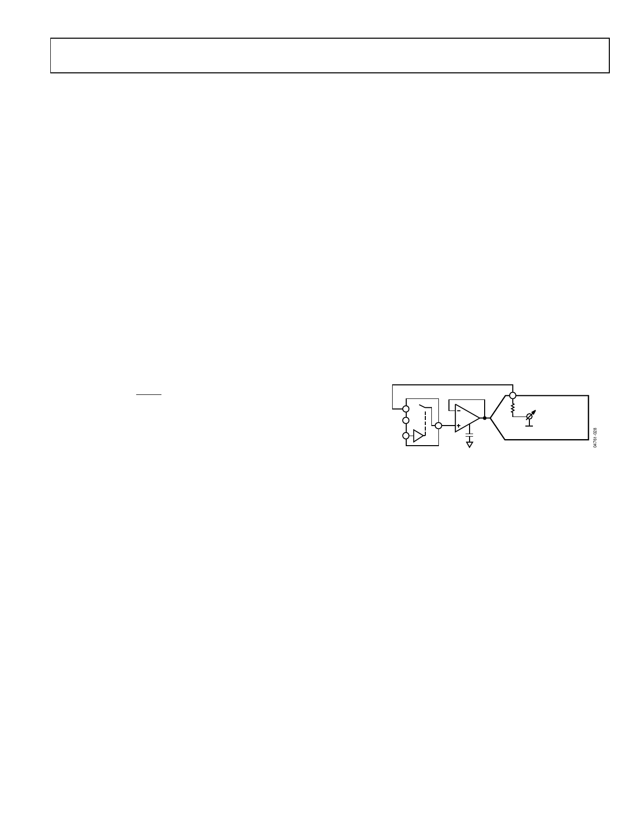
Temperature Sensor
The TEMP pin measures the temperature of the AD7641. To
improve the calibration accuracy over the temperature range,
the output of the TEMP pin is applied to one of the inputs of
the analog switch (such as, ADG779), and the ADC itself is
used to measure its own temperature. This configuration is
shown in Figure 27.
ADG779
TEMP
ANALOG INPUT
(UNIPOLAR)
IN+
AD8021 CC
TEMPERATURE
SENSOR
AD7641
Figure 27. Use of the Temperature Sensor
Rev. 0 | Page 19 of 28
Share Link: 