TDF8599 데이터 시트보기 (PDF) - NXP Semiconductors.
부품명
상세내역
일치하는 목록
TDF8599 Datasheet PDF : 52 Pages
| |||
NXP Semiconductors
TDF8599
Class-D power amplifier with load diagnostics
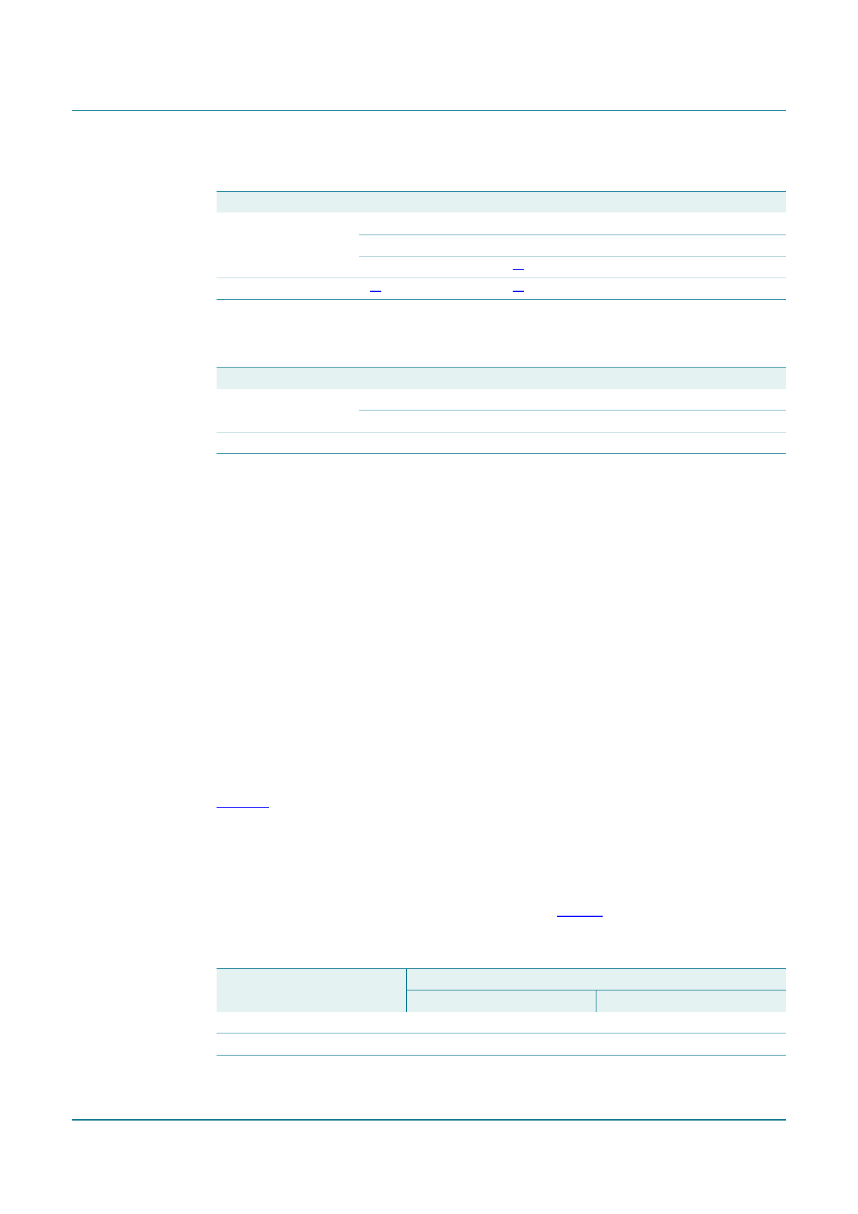
Table 4. I2C-bus mode operation
Pin EN
Bit IB1[D0]
S2 closed
1
1
0
S2 open
X[1]
[1] X = do not care
Bit IB2[D0]
0
1
X[1]
X[1]
Mode
Operating mode
Mute mode
Standby mode
off
Table 5. Non-I2C-bus mode operation
Pin EN
Bit IB2[D0]
S2 closed
S1 open
S2 closed
S2 open
do not care
Mode
Operating mode
Mute mode
off
8.3 Pulse-width modulation frequency
The output signal from the amplifier is a PWM signal with a switching frequency of fosc.
This frequency is set by connecting a resistor (Rosc) between pins OSCSET and AGND.
The optimal clock frequency setting is between 300 kHz and 400 kHz. Connecting a
resistor with a value of 39 kΩ, for example, sets the clock frequency to 320 kHz. The
external capacitor (Cosc) has no influence on the oscillator frequency. It does however,
reduce jitter and sensitivity to disturbance. Using a 2nd order LC demodulation filter in the
application generates an analog audio signal across the loudspeaker.
8.3.1 Master and slave mode selection
In a master and slave configuration, multiple TDF8599 devices are daisy-chained together
in one audio application with a single device providing the clock frequency signal for the
other devices. In this situation, it is recommended that the oscillators of all devices are
synchronized for optimum EMI behavior as follows:
All OSCIO pins are connected together and one TDF8599 in the application is configured
as the clock-master. All other TDF8599 devices are configured as clock-slaves (see
Figure 6).
• The clock-master pin OSCIO is configured as the oscillator output. When a resistor
(Rosc) is connected between pins OSCSET and AGND, the TDF8599 is in Master
mode.
• The clock-slave pins OSCIO are configured as the oscillator inputs. When pin
OSCSET is directly connected to pin AGND (see Table 6), the TDF8599 is in Slave
mode.
Table 6.
Mode
Master
Slave
Mode setting OSCIO
Settings
Pin OSCSET
Rosc > 26 kΩ
Rosc = 0 kΩ; shorted to AGND
Pin OSCIO
output
input
TDF8599_1
Product data sheet
Rev. 01 — 13 November 2008
© NXP B.V. 2008. All rights reserved.
8 of 52
Share Link: 