TDF8599 데이터 시트보기 (PDF) - NXP Semiconductors.
부품명
상세내역
일치하는 목록
TDF8599 Datasheet PDF : 52 Pages
| |||
NXP Semiconductors
TDF8599
Class-D power amplifier with load diagnostics
The TDF8599 includes integrated common circuits for all channels such as the oscillator,
all reference sources, mode functionality and a digital timing manager. In addition, the
built-in protection includes thermal foldback, temperature, overcurrent and overvoltage
(load dump).
The TDF8599 operates in either I2C-bus mode or non-I2C-bus mode. In I2C-bus mode,
DC load detection, frequency hopping and extended configurability are provided together
with enhanced diagnostic information.
8.2 Mode selection
The mode pins EN and SEL_MUTE enable mute state, I2C-bus mode and Operating
mode switching.
Pin SEL_MUTE is used to mute and demute the device and must be connected to an
external capacitor. This capacitor generates a time constant which is used to ensure
smooth fade-in and fade-out of the input signal.
When pin EN is LOW, the TDF8599 is off and the supply current is at its lowest value
(typically 2 µA). When off, the TDF8599 is completely deactivated and will not react to
I2C-bus commands. The TDF8599 is enabled when pin EN is HIGH.
A resistor connected between pin ADS and ground determines if the TDF8599 is in
I2C-bus mode or in non-I2C-bus mode (see Section 9). I2C-bus mode is selected by
leaving the connection between pin ADS and pin GND open. In I2C-bus mode with pin EN
HIGH, the TDF8599 is in Standby mode and will wait for further commands.
Non-I2C-bus mode is selected by connecting pin ADS to pin GND. In non-I2C-bus mode,
the default TDF8599 state is Mute mode. The amplifiers switch idle (50 % duty cycle) and
the audio signal is suppressed at the output. In addition, the capacitor (CSVRR) is charged
to half the supply voltage. To enter Operating mode, pin SEL_MUTE must be released
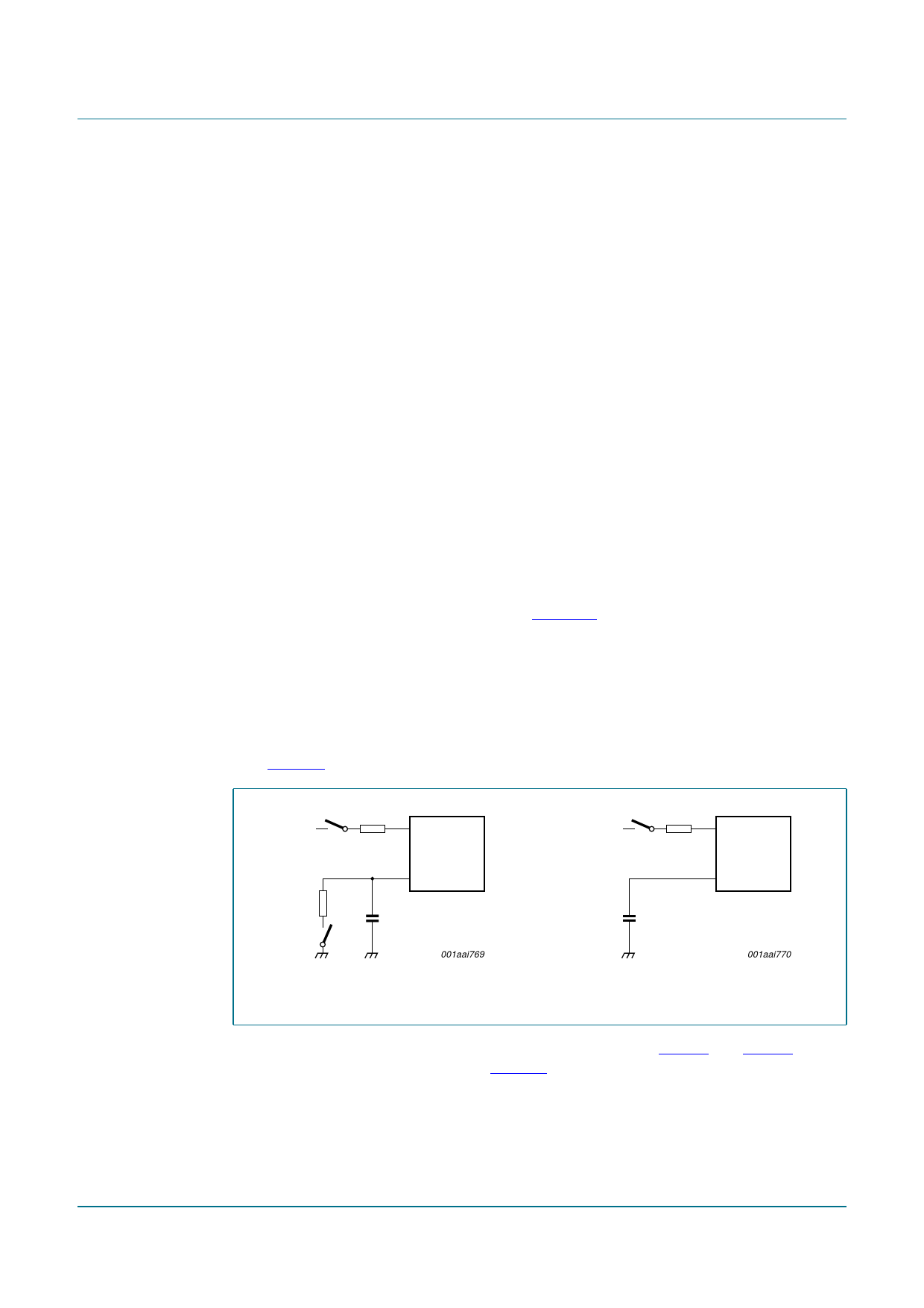
(see Figure 4) and capacitor (CON) charged by an internal pull-up.
S2
EN
3.3 V
TDF8599
SEL_MUTE
S2
EN
3.3 V
TDF8599
SEL_MUTE
CON
S1
001aai769
CON
001aai770
a. non-I2C-bus mode
Fig 4. Mode selection
b. I2C-bus mode
I2C-bus mode and non-I2C-bus mode control are described in Table 4 and Table 5.
Switches S1 and S2 are illustrated in Figure 4.
TDF8599_1
Product data sheet
Rev. 01 — 13 November 2008
© NXP B.V. 2008. All rights reserved.
7 of 52
Share Link: 