MT9042 데이터 시트보기 (PDF) - Mitel Networks
부품명
상세내역
일치하는 목록
MT9042 Datasheet PDF : 16 Pages
| |||
Preliminary Information
MT9042
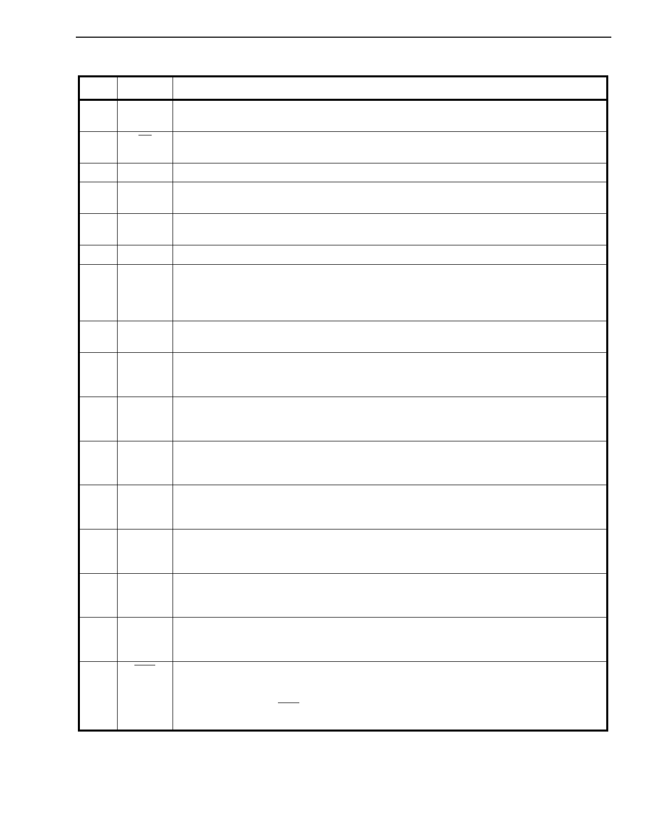
Pin Description (continued)
Pin #
13
14
15
16
17
18
19
20
21
22
23
24
25
26
27
28
Name
Description
C2 Clock 2.048 MHz (CMOS compatible). This output is a 2.048 MHz (E1) output clock
locked to the selected reference input signal.
C4 Clock 4.096 MHz (CMOS compatible). This output is a 4.096 MHz output clock locked to
the selected reference input signal.
VSS Negative Power Supply Voltage. Nominally 0 Volts.
C8 Clock 8.192 MHz (CMOS compatible). This output is an 8.192 MHz output clock locked to
the selected reference input signal.
C16 Clock 16.384 MHz (CMOS compatible). This output is a 16.384 MHz output clock locked
to the selected reference input signal.
VDD Positive Supply Voltage. Nominally +5 volts.
GTi Guard Time Input (TTL Level Schmitt Trigger). This TTL level Schmitt trigger input is
used to determine the threshold level of the RC generated (guard) time constant. This
function filters out unwanted rearrangements between the PRI and SEC reference input
signals.
GTo Guard Time Output (CMOS compatible). This is a CMOS buffered output used to drive the
external RC generated (guard) time constant circuit.
LOSS2 Reference Loss Indicator - 2 Input (TTL compatible). This input, in conjunction with
LOSS1, comprises a set of signals which control the event driven state machine when the
PLL is operating in AUTOMATIC mode (see Table 4).
LOSS1 Reference Loss Indicator - 1 Input (TTL compatible). This input, in conjunction with
LOSS2, comprises a set of signals which control the event driven state machine when the
PLL is operating in AUTOMATIC mode (see Table 4).
MS2
Mode Select - 2 Input (TTL compatible). This input, in conjunction with MS1, selects the
PLL mode of operation (i.e.,NORMAL, HOLDOVER, FREERUN, or AUTOMATIC; see Table
1).
MS1
Mode Select - 1 Input (TTL compatible). This input, in conjunction with MS2, selects the
PLL mode of operation (i.e., NORMAL, HOLDOVER, FREERUN, or AUTOMATIC; see Table
1).
RSEL
Input Reference Select (TTL compatible). When LOW this input selects PRI as the
reference input signal, and when HIGH, selects SEC as the reference input signal (see Table
2).
FSEL2 Frequency Select - 2 Input (TTL compatible). This input, in conjunction with FSEL1,
selects the frequency of the input reference source (i.e., 8 kHz, 1.544 MHz, or 2.048 MHz;
see Table 3).
FSEL1
RST
Frequency Select - 1 Input (TTL compatible). This input, in conjunction with FSEL2,
selects the frequency of the input reference source (i.e., 8 kHz, 1.544 MHz, or 2.048 MHz;
see Table 3).
Reset (TTL compatible). This input (active LOW) puts the MT9042 in its reset state. To
guarantee proper operation, the device must be reset after power-up. The time constant for
a power-up reset circuit must be a minimum of five times the rise time of the power supply. In
normal operation, the RST pin must be held low for a minimum of 60 nsec to reset the
device.
3-99
Share Link: 