HMC404(2001) 데이터 시트보기 (PDF) - Hittite Microwave
부품명
상세내역
일치하는 목록
HMC404 Datasheet PDF : 8 Pages
| |||
v02.1001
MICROWAVE CORPORATION
HMC404
GaAs MMIC SUB-HARMONICALLY
PUMPED IRM MIXER, 26 - 33 GHz
Assembly Diagrams
5
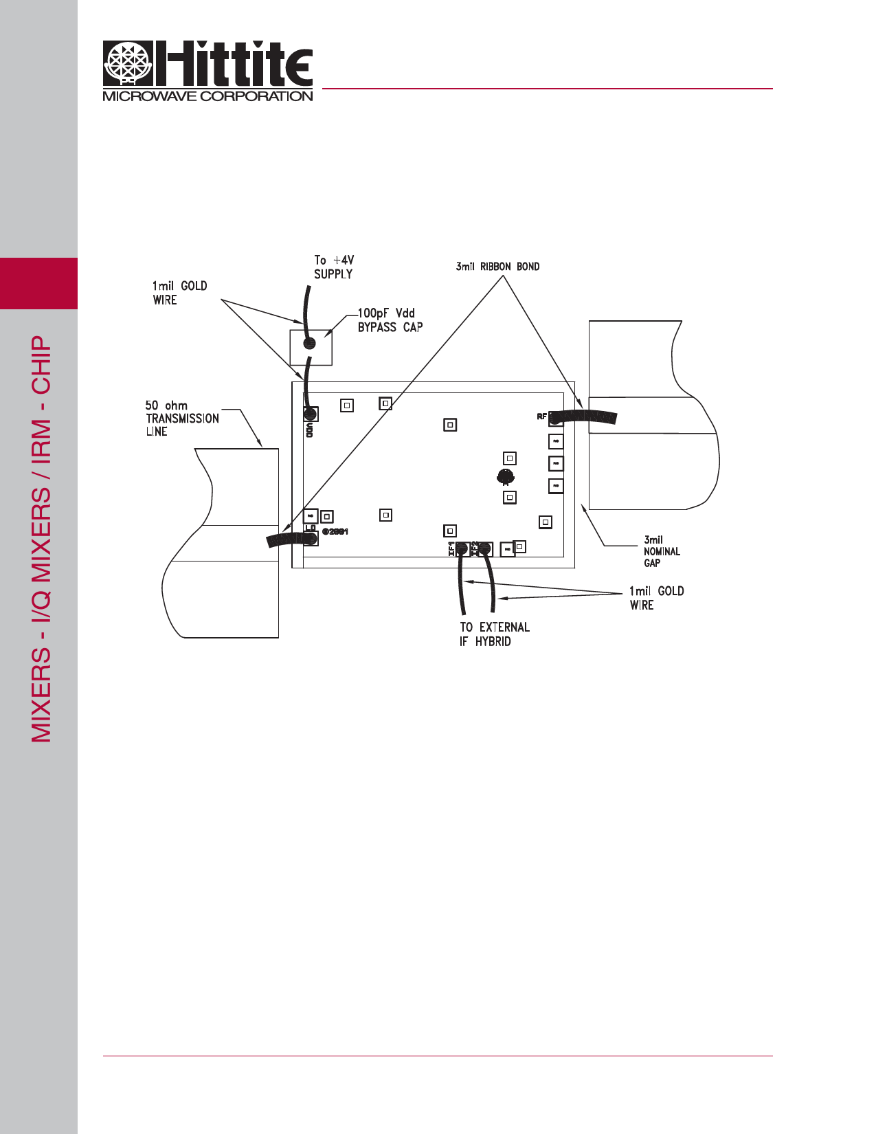
Mounting & Bonding Techniques for Millimeterwave GaAs MMICs
The die should be attached directly to the ground plane eutectically or with conductive epoxy (see HMC general Han-
dling, Mounting, Bonding Note).
50 Ohm Microstrip transmission lines on 0.127mm (5 mil) thick alumina thin film substrates are recommended for bring-
ing RF to and from the chip (Figure 1). If 0.254mm (10 mil) thick alumina thin film substrates must be used, the die
should be raised 0.150mm (6 mils) so that the surface of the die is coplanar with the surface of the substrate. One
way to accomplish this is to attach the 0.102mm (4 mil) thick die to a 0.150mm (6 mil) thick molybdenum heat spreader
(moly-tab) which is then attached to the ground plane (Figure 2).
Microstrip substrates should be brought as close to the die as possible in order to minimize ribbon bond length. Typical
die-to-substrate spacing is 0.076mm (3 mils). Gold ribbon of 0.075 mm (3 mil) width and minimal length <0.31 mm (<12
mils) is recommended to minimize inductance on RF, LO & IF ports.
An RF bypass capacitor should be used on the Vdd input. A 100 pF single layer capacitor (mounted eutectically or by
conductive epoxy) placed no further than 0.762mm (30 Mils) from the chip is recommended.
3 mil Ribbon Bond
3 mil Ribbon Bond
5 - 124
For price, delivery, and to place orders, please contact Hittite Microwave Corporation:
12 Elizabeth Drive, Chelmsford, MA 01824 Phone: 978-250-3343 Fax: 978-250-3373
Order Online at www.hittite.com
Share Link: 