TA76432FT(2002) 데이터 시트보기 (PDF) - Toshiba
부품명
상세내역
일치하는 목록
TA76432FT Datasheet PDF : 12 Pages
| |||
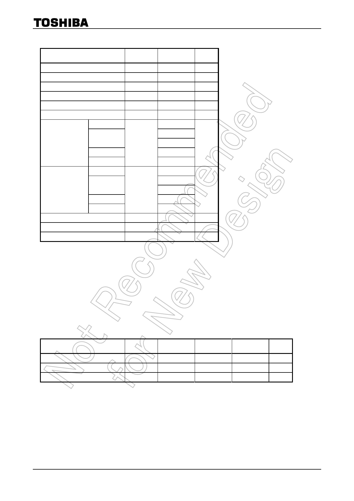
Recommended Operating Conditions
Characteristics
Cathode voltage
Cathode current
Operating temperature
Symbol
VKA
IK
Topr
Min
VREF
0.5
-40
TA76432FT/FC/F/FR/S
Typ.
Max
Unit
¾
19
V
¾
15
mA
¾
85
°C
Electrical Characteristics (Unless otherwise specified, Ta = 25°C, IK = 5 mA)
Characteristics
Reference voltage
Deviation of reference input voltage
over temperature
Ratio of change in reference input
voltage to the change in cathode
voltage
Reference Input current
Deviation of reference input current
over temperature
Minimum cathode current for
regulation
Off-State cathode current
Dynamic impedance
Symbol
Test Condition
VREF
VREF (dev)
DVREF/DV
IREF
IREF (dev)
VKA = VREF
0°C <= Ta <= 85°C, VKA = VREF
VREF <= VKA <= 5 V
5 V <= VKA <= 19 V
VKA = VREF
0°C <= Ta <= 85°C, VKA = VREF,
R1 = 10 kW, R2 = ¥
IKmin
VKA = VREF
IKoff
ïZKAï
VKA = 19 V, VREF = 0 V
0V.K5Am=AV<=REIKF,<=f
<= 1 kHz,
15 mA
Min Typ. Max Unit
1.242 1.26 1.278 V
¾
3
15
mV
¾
0.5 2.5
mV/V
¾
0.3 2.0
¾
2
4
mA
¾
0.3 1.2
mA
¾
0.2 0.5 mA
¾
¾
1.0
mA
¾
0.2 0.5
W
The deviation parameters VREF (dev) and IREF (dev) are defined as the maximum variation of the VREF and IREF over the
rated temperature range.
The average temperature coefficient of the VREF is defined as:
VREF
max
min
VREF (dev)
çæ VREF (dev) ´ 106 ÷ö
aVREF = ççè
VREF @25°C
DTa
÷÷ø
ppm °C
DTa
Application Circuit Example
Error amplification circuit for switching power supply
Photo-
coupler
VOUT
GND
Shunt regulator
This circuit amplifies the difference between the switching power supply’s secondary output voltage and the shunt
regulator’s reference voltage. It then feeds the amplified voltage back to the primary input voltage via the
photocoupler.
4
2002-07-12
Share Link: 