TDA1175P 데이터 시트보기 (PDF) - STMicroelectronics
부품명
상세내역
일치하는 목록
TDA1175P Datasheet PDF : 13 Pages
| |||
TDA1175P
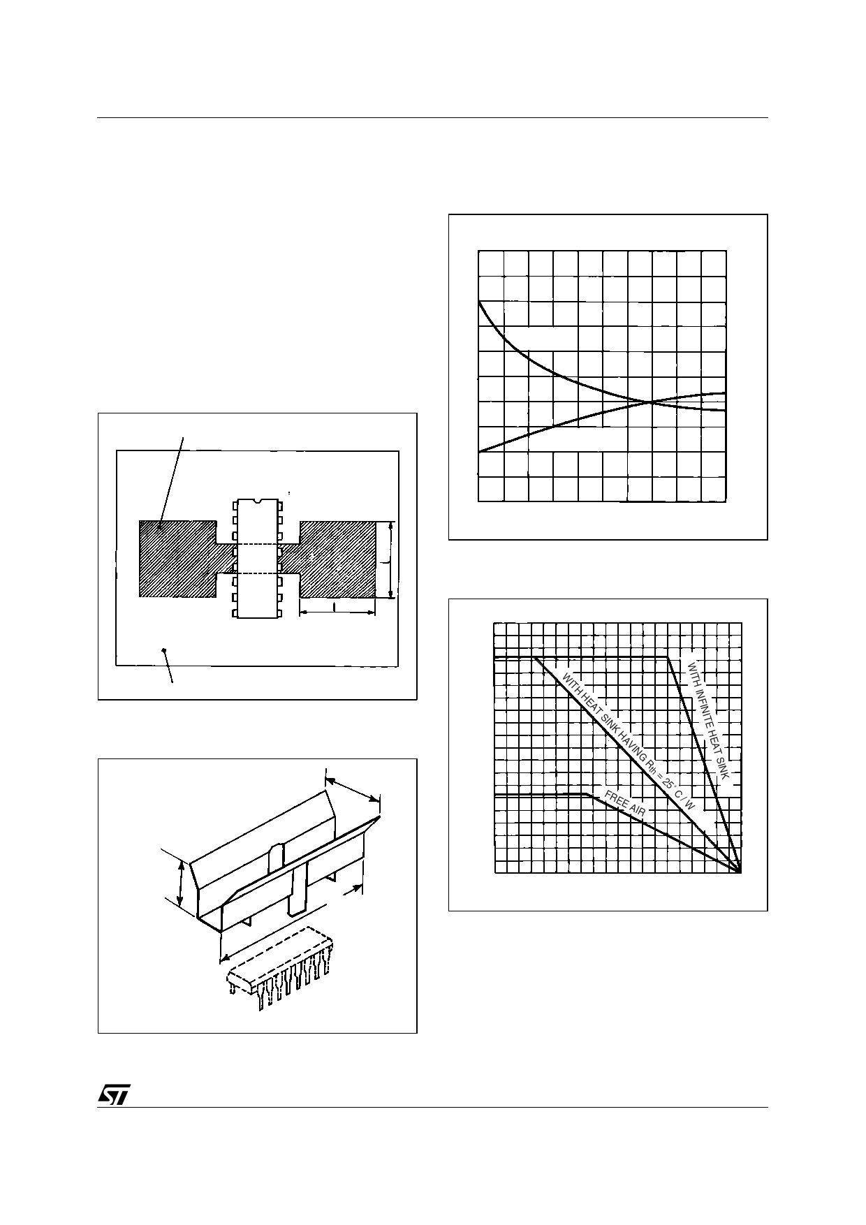
MOUNTING INSTRUCTION
The Rth (j-a) can be reduced by soldering the GND
pins to a suitable copper area of the printed circuit
board (Figure 11) or to an external heatsink (Fig-
ure 12).
The diagram of Figure 13 shows the maximum dis-
sipable power Ptot and the Rth (j-a) as a function of
the side "I" of two equal square copper areas hav-
ing a thicknessof 35µ (1.4 mils).
During soldering the pins temperature must not
exceed 260°C and the soldering time must not be
longer than 12 seconds.
The external heatsink or printed circuit copper
area must be connected to electrical ground.
Figure 11. Example of P.C. Board Copper Area
COPPER AREA 35µ THICKNESS
Figure 13. Maximum Power Dissipation and
Junction-ambient Thermal Resistance versus
"I"
G-3558
Ptot
Rth
(W)
(˚C/W)
4
80
Rth j - amb
3
60
2
40
1
Ptot (Tamb = 70˚C)
20
0
0
0
10
20
30
40 l (mm)
P.C. BOARD
S-3181
Figure 12. External Heatsink Mounting
Example
17.0 mm
11.9 mm
38.0 mm
Figure 14. Maximum Allowable Power
Dissipation versus Ambient Temperature
G-3559/2
Ptot
4
3
2
FREE AIR
1
0
-50
0
50
100 Tamb(˚C)
S-3474
9/13
Share Link: 