AV9248-127 데이터 시트보기 (PDF) - Integrated Circuit Systems
부품명
상세내역
일치하는 목록
AV9248-127 Datasheet PDF : 14 Pages
| |||
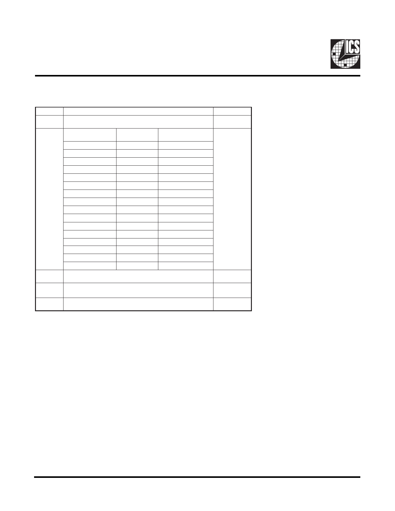
ICS9248 - 127
Serial Configuration Command Bitmap
Byte0: Functionality and Frequency Select Register (default = 0)
Bit
Bit 7
Bit
[2, 6:4]
Bit 3
Bit 1
Bit 0
Description
0 - ±0.25% Center Spread Spectrum Modulation
1 - 0 to -0.5% Down Spread Spectrum Modulation
Bit [2, 6:4]
CPUCLK
(MHz)
PCICLK
(MHz)
0000
124.00
41.33
0001
120.00
40.00
0010
114.99
38.33
0011
109.99
36.66
0100
105.00
35.00
0101
83.31
41.65
0110
80.00
40.00
0111
75.00
37.50
1000
100.00
33.33
1001
95.19
31.73
1010
83.31
27.77
1011
97.00
32.33
1100
90.00
30.00
1101
70.00
35.00
1110
66.82
33.41
1111
60.00
30.00
0 - Frequency is selected by hardware select, latched inputs
1 - Frequency is selected by Bit [2, 6:4]
0 - Normal
1 - Spread Spectrum Enabled
0 - Running
1- Tristate all outputs
PWD
1
Note1
0,010
0
Note 2
1
0
Note 1. Default at Power-up will be for latched logic inputs to define frequency.
I2C readback of the power up default indicate the revision ID code in bit 2,
6:4 as shown.
Note 2. To ensure normal operation, Bit 7 needs to be "0" when in non - spread spectrum
mode (Bit 1 = 0).
Note: PWD = Power-Up Default.
I2C is a trademark of Philips Corporation
4
Share Link: 