NCP1547 데이터 시트보기 (PDF) - ON Semiconductor
부품명
상세내역
일치하는 목록
NCP1547 Datasheet PDF : 15 Pages
| |||
NCP1547
Figure 15 to Figure 18 show the output ripple of a 5.0 V
to 3.3 V/500 mA regulator using 22 mH inductor and various
capacitor types. At the switching frequency, the low ESR
and ESL make the ceramic capacitors behave capacitively
as shown in Figure 15. Additional paralleled ceramic
capacitors will further reduce the ripple voltage, but
inevitably increase the cost. “POSCAP”, manufactured by
SANYO, is a solid electrolytic capacitor. The anode is
sintered tantalum and the cathode is a highly conductive
polymerized organic semiconductor. TPC series, featuring
low ESR and low profile, is used in the measurement of
Figure 16. It is shown that POSCAP presents a good balance
of capacitance and ESR, compared with a ceramic capacitor.
In this application, the low ESR generates less than 5.0 mV
of ripple and the ESL is almost unnoticeable. The ESL of the
through−hole OS−CON capacitor give rise to the inductive
impedance. It is evident from Figure 17 which shows the
step rise of the output ripple on the switch turn−on and large
spike on the switch turn−off. The ESL prevents the output
capacitor from quickly charging up the parasitic capacitor of
the inductor when the switch node is pulled below ground
through the catch diode conduction. This results in the spike
associated with the falling edge of the switch node. The D
package tantalum capacitor used in Figure 18 has the same
footprint as the POSCAP, but doubles the height. The ESR
of the tantalum capacitor is apparently higher than the
POSCAP. The electrolytic and tantalum capacitors provide
a low−cost solution with compromised performance. The
reliability of the tantalum capacitor is not a serious concern
for output filtering because the output capacitor is usually
free of surge current and voltage.
Diode Selection
The diode in the buck converter provides the inductor
current path when the power switch turns off. The peak
reverse voltage is equal to the maximum input voltage. The
peak conducting current is clamped by the current limit of
the IC. The average current can be calculated from:
ID(AVG)
+
IO(VIN *
VIN
VO)
The worse case of the diode average current occurs during
maximum load current and maximum input voltage. For the
diode to survive the short circuit condition, the current rating
of the diode should be equal to the Foldback Current Limit.
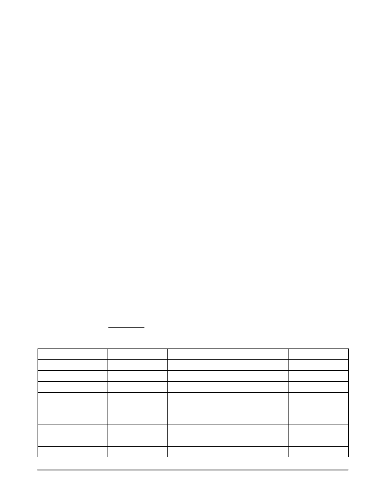
See Table 1 for Schottky diodes from ON Semiconductor
which are suggested for use with the NCP1547 regulator.
Inductor Selection
When choosing inductors, one might have to consider
maximum load current, core and copper losses, component
height, output ripple, EMI, saturation and cost. Lower
inductor values are chosen to reduce the physical size of the
inductor. Higher value cuts down the ripple current, core
losses and allows more output current. For most
applications, the inductor value falls in the range between
2.2 mH and 22 mH. The saturation current ratings of the
inductor shall not exceed the IL(PK), calculated according to
IL(PK)
+
IO
)
VO(VIN * VO)
2(fS)(L)(VIN)
The DC current through the inductor is equal to the load
current. The worse case occurs during maximum load
current. Check the vendor’s spec to adjust the inductor value
under current loading. Inductors can lose over 50% of
inductance when it nears saturation.
The core materials have a significant effect on inductor
performance. The ferrite core has benefits of small physical
size, and very low power dissipation. But be careful not to
operate these inductors too far beyond their maximum
ratings for peak current, as this will saturate the core.
Powered Iron cores are low cost and have a more gradual
saturation curve. The cores with an open magnetic path, such
as rod or barrel, tend to generate high magnetic field
radiation. However, they are usually cheap and small. The
cores providing a close magnetic loop, such as pot−core and
toroid, generate low electro−magnetic interference (EMI).
There are many magnetic component vendors providing
standard product lines suitable for the NCP1547. Table 2
lists three vendors, their products and contact information.
Table 1.
Part Number
VBREAKDOWN (V)
IAVERAGE (A)
V(F) (V) @ IAVERAGE
Package
1N5817
20
1.0
0.45
Axial Lead
1N5818
30
1.0
0.55
Axial Lead
1N5819
40
1.0
0.6
Axial Lead
MBR0520
20
0.5
0.385
SOD−123
MBR0530
30
0.5
0.43
SOD−123
MBR0540
40
0.5
0.53
SOD−123
MBRS120
20
1.0
0.55
SMB
MBRS130
30
1.0
0.395
SMB
MBRS140
40
1.0
0.6
SMB
http://onsemi.com
12
Share Link: 