NCP1547 데이터 시트보기 (PDF) - ON Semiconductor
부품명
상세내역
일치하는 목록
NCP1547 Datasheet PDF : 15 Pages
| |||
NCP1547
them for some low cost designs. Electrolytic capacitors are
physically large, and not used in applications where the size,
and especially height is the major concern.
Ceramic capacitors are now available in values over 10 mF.
Since the ceramic capacitor has low ESR and ESL, a single
ceramic capacitor can be adequate for both low frequency
and high frequency noises. The disadvantage of ceramic
capacitors are their high cost. Solid tantalum capacitors can
have low ESR and small size. However, the reliability of the
tantalum capacitor is always a concern in the application
where the capacitor may experience surge current.
Output Capacitor
In a buck converter, the requirements on the output
capacitor are not as critical as those on the input capacitor.
The current to the output capacitor comes from the inductor
and thus is triangular. In most applications, this makes the
RMS ripple current not an issue in selecting output
capacitors.
The output ripple voltage is the sum of a triangular wave
caused by ripple current flowing through ESR, and a square
wave due to ESL. Capacitive reactance is assumed to be
small compared to ESR and ESL. The peak to peak ripple
current of the inductor is:
IP
*
P
+
VO(VIN * VO)
(VIN)(L)(fS)
VRIPPLE(ESR), the output ripple due to the ESR, is equal
to the product of IP−P and ESR. The voltage developed
across the ESL is proportional to the di/dt of the output
capacitor. It is realized that the di/dt of the output capacitor
is the same as the di/dt of the inductor current. Therefore,
when the switch turns on, the di/dt is equal to (VIN − VO)/L,
and it becomes VO/L when the switch turns off. The total
ripple voltage induced by ESL can then be derived from
VRIPPLE(ESL)
+
ESL(VLO)
)
ESL(VIN
*
L
VO)
+
ESL(VLIN)
The total output ripple is the sum of the VRIPPLE(ESR) and
VRIPPLE(ESL).
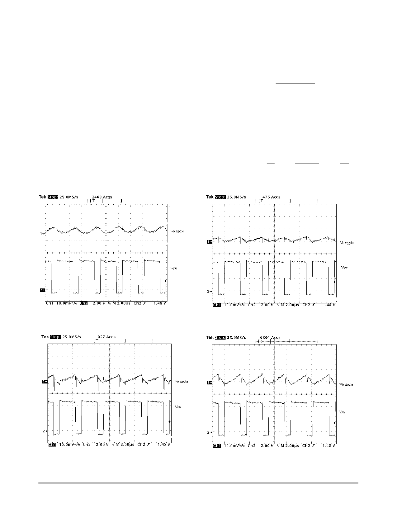
Figure 15. The Output Voltage Ripple Using Two 10 mF
Ceramic Capacitors in Parallel
Figure 16. The Output Voltage Ripple Using One
100 mF POSCAP Capacitor
Figure 17. The Output Voltage Ripple Using
One 100 mF OS−CON
Figure 18. The Output Voltage Ripple Using
One 100 mF Tantalum Capacitor
http://onsemi.com
11
Share Link: 