NCP1547(2007) 데이터 시트보기 (PDF) - ON Semiconductor
부품명
상세내역
일치하는 목록
NCP1547 Datasheet PDF : 13 Pages
| |||
NCP1547
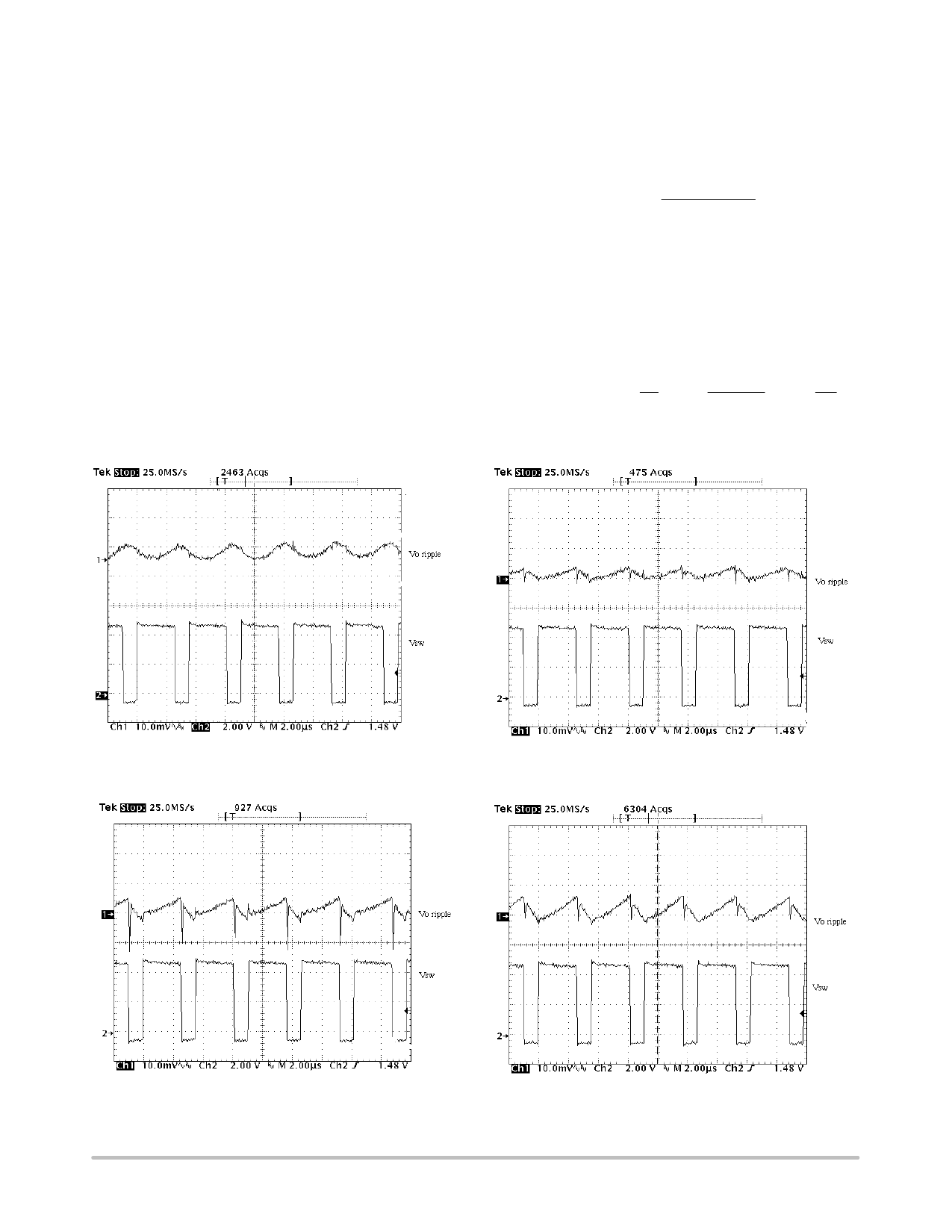
Figure 12. The Output Voltage Ripple Using Two 10 mF
Ceramic Capacitors in Parallel
Figure 13. The Output Voltage Ripple Using One
100 mF POSCAP Capacitor
Figure 14. The Output Voltage Ripple Using
One 100 mF OS−CON
Figure 12 to Figure 15 show the output ripple of a 5.0 V
to 3.3 V/500 mA regulator using 22 mH inductor and various
capacitor types. At the switching frequency, the low ESR
and ESL make the ceramic capacitors behave capacitively
as shown in Figure 12. Additional paralleled ceramic
capacitors will further reduce the ripple voltage, but
inevitably increase the cost. “POSCAP”, manufactured by
SANYO, is a solid electrolytic capacitor. The anode is
sintered tantalum and the cathode is a highly conductive
polymerized organic semiconductor. TPC series, featuring
low ESR and low profile, is used in the measurement of
Figure 13. It is shown that POSCAP presents a good balance
of capacitance and ESR, compared with a ceramic capacitor.
In this application, the low ESR generates less than 5.0 mV
of ripple and the ESL is almost unnoticeable. The ESL of the
through−hole OS−CON capacitor give rise to the inductive
impedance. It is evident from Figure 14 which shows the
step rise of the output ripple on the switch turn−on and large
spike on the switch turn−off. The ESL prevents the output
capacitor from quickly charging up the parasitic capacitor of
Figure 15. The Output Voltage Ripple Using
One 100 mF Tantalum Capacitor
the inductor when the switch node is pulled below ground
through the catch diode conduction. This results in the spike
associated with the falling edge of the switch node. The D
package tantalum capacitor used in Figure 15 has the same
footprint as the POSCAP, but doubles the height. The ESR
of the tantalum capacitor is apparently higher than the
POSCAP. The electrolytic and tantalum capacitors provide
a low−cost solution with compromised performance. The
reliability of the tantalum capacitor is not a serious concern
for output filtering because the output capacitor is usually
free of surge current and voltage.
Diode Selection
The diode in the buck converter provides the inductor
current path when the power switch turns off. The peak
reverse voltage is equal to the maximum input voltage. The
peak conducting current is clamped by the current limit of
the IC. The average current can be calculated from:
ID(AVG)
+
IO(VIN *
VIN
VO)
http://onsemi.com
11
Share Link: 