NCP1547(2007) 데이터 시트보기 (PDF) - ON Semiconductor
부품명
상세내역
일치하는 목록
NCP1547 Datasheet PDF : 13 Pages
| |||
NCP1547
The worse case of the diode average current occurs during
maximum load current and maximum input voltage. For the
diode to survive the short circuit condition, the current rating
of the diode should be equal to the Foldback Current Limit.
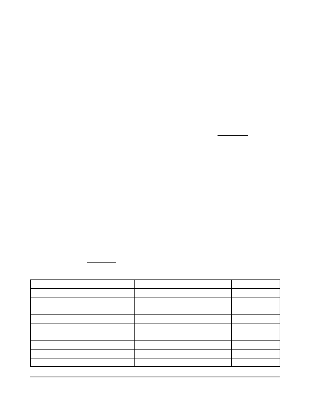
See Table 1 for Schottky diodes from ON Semiconductor
which are suggested for use with the NCP1547 regulator.
Inductor Selection
When choosing inductors, one might have to consider
maximum load current, core and copper losses, component
height, output ripple, EMI, saturation and cost. Lower
inductor values are chosen to reduce the physical size of the
inductor. Higher value cuts down the ripple current, core
losses and allows more output current. For most
applications, the inductor value falls in the range between
2.2 mH and 22 mH. The saturation current ratings of the
inductor shall not exceed the IL(PK), calculated according to
IL(PK)
+
IO
)
VO(VIN * VO)
2(fS)(L)(VIN)
The DC current through the inductor is equal to the load
current. The worse case occurs during maximum load
current. Check the vendor’s spec to adjust the inductor value
under current loading. Inductors can lose over 50% of
inductance when it nears saturation.
The core materials have a significant effect on inductor
performance. The ferrite core has benefits of small physical
size, and very low power dissipation. But be careful not to
operate these inductors too far beyond their maximum
ratings for peak current, as this will saturate the core.
Powered Iron cores are low cost and have a more gradual
saturation curve. The cores with an open magnetic path, such
as rod or barrel, tend to generate high magnetic field
radiation. However, they are usually cheap and small. The
cores providing a close magnetic loop, such as pot−core and
toroid, generate low electro−magnetic interference (EMI).
There are many magnetic component vendors providing
standard product lines suitable for the NCP1547. Table 2
lists three vendors, their products and contact information.
Table 1.
Part Number
1N5817
VBREAKDOWN (V)
20
IAVERAGE (A)
1.0
V(F) (V) @ IAVERAGE
0.45
Package
Axial Lead
1N5818
30
1.0
0.55
Axial Lead
1N5819
40
1.0
0.6
Axial Lead
MBR0520
20
0.5
0.385
SOD−123
MBR0530
30
0.5
0.43
SOD−123
MBR0540
40
0.5
0.53
SOD−123
MBRS120
20
1.0
0.55
SMB
MBRS130
30
1.0
0.395
SMB
MBRS140
40
1.0
0.6
SMB
Table 2.
Vendor
Coiltronics
Coilcraft
Pulse
Product Family
UNI−Pac1/2: SMT, barrel
THIN−PAC: SMT, toroid, low profile
CTX: Leaded, toroid
DO1608: SMT, barrel
DS/DT 1608: SMT, barrel, magnetically shielded
DO3316: SMT, barrel
DS/DT 3316: SMT, barrel, magnetically shielded
DO3308: SMT, barrel, low profile
−
Web Site
www.coiltronics.com
www.coilcraft.com
www.pulseeng.com
Telephone
(516) 241−7876
(800) 322−2645
(619) 674−8100
ORDERING INFORMATION
Device
Package
Shipping†
NCP1547MNR2G
DFN18
(Pb−Free)
2500 Units / Tape & Reel
†For information on tape and reel specifications, including part orientation and tape sizes, please refer to our Tape and Reel Packaging
Specifications Brochure, BRD8011/D.
http://onsemi.com
12
Share Link: 