CS8164 데이터 시트보기 (PDF) - Cherry semiconductor
부품명
상세내역
일치하는 목록
CS8164 Datasheet PDF : 8 Pages
| |||
Circuit Description: continued
to bias VOUT2 up to this point. Approximately 60µA will
suffice, resulting in a 10k½ external resistor for most appli-
cations.
VIN
High Current Output
Unlike the standby regulated output, which must remain
on whenever possible, the high current regulated output is
fault protected against overvoltage and also incorporates
thermal shutdown. If the input voltage rises above
approximately 30V (e.g., load dump), this output will
automatically shutdown. This protects the internal circuit-
ry and enables the IC to survive higher voltage transients
than would otherwise be expected. Thermal shutdown is
effective against die overheating since the high current out-
put is the dominant source of power dissipation in the IC.
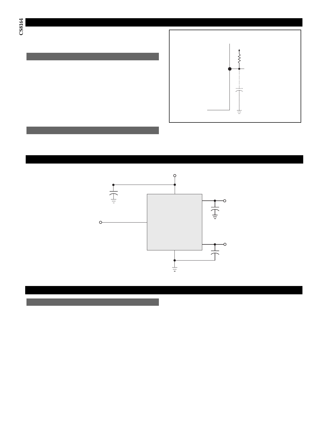
VOUT2
RD
10kW
VOUT2
+
C3
ENABLE
Disabling VOUT2 when it is not needed. C3 is no longer needed.
The enable function controls VOUT1 When ENABLE is high
(5V), VOUT1 is on. When ENABLE is low, VOUT1 is off.
Test & Application Circuit
C1*
0.1 mF
VIN
VOUT1
CS8164
ENABLE
+
C2**
10mF
NOTES:
* C1 required if regulator is located far from power
supply filter.
** C2, C3 required for stability.
Gnd
VOUT2
+
C3**
10mF
Application Notes
Stability Considerations
The output or compensation capacitor helps determine
three main characteristics of a linear regulator: start-up
delay, load transient response and loop stability.
The capacitor value and type should be based on cost,
availability, size and temperature constraints. A tantalum
or aluminum electrolytic capacitor is best, since a film or
ceramic capacitor with almost zero ESR can cause instabil-
ity. The aluminum electrolytic capacitor is the least expen-
sive solution, but, if the circuit operates at low tempera-
tures (-25¡C to -40¡C), both the value and ESR of the
capacitor will vary considerably. The capacitor manufac-
turers data sheet usually provides this information.
The value for each output capacitor shown in the test and
applications circuit should work for most applications,
however it is not necessarily the optimized solution.
To determine acceptable values for C2 and C3 a particular
application, start with a tantalum capacitor of the recom-
mended value and work towards a less expensive alterna-
tive part for each output.
Step 1: Place the completed circuit with the tantalum
capacitors of the recommended values in an environmen-
tal chamber at the lowest specified operating temperature
and monitor the outputs with an oscilloscope. A decade
box connected in series with the capacitor C2 will simulate
the higher ESR of an aluminum capacitor. Leave the
decade box outside the chamber, the small resistance
added by the longer leads is negligible.
Step 2: With the input voltage at its maximum value,
increase the load current slowly from zero to full load on
the output under observation. look for oscillations on the
output. If no oscillations are observed, the capacitor is
large enough to ensure a stable design under steady state
conditions.
6
Share Link: 