GS1500 데이터 시트보기 (PDF) - Gennum -> Semtech
부품명
상세내역
일치하는 목록
GS1500 Datasheet PDF : 17 Pages
| |||
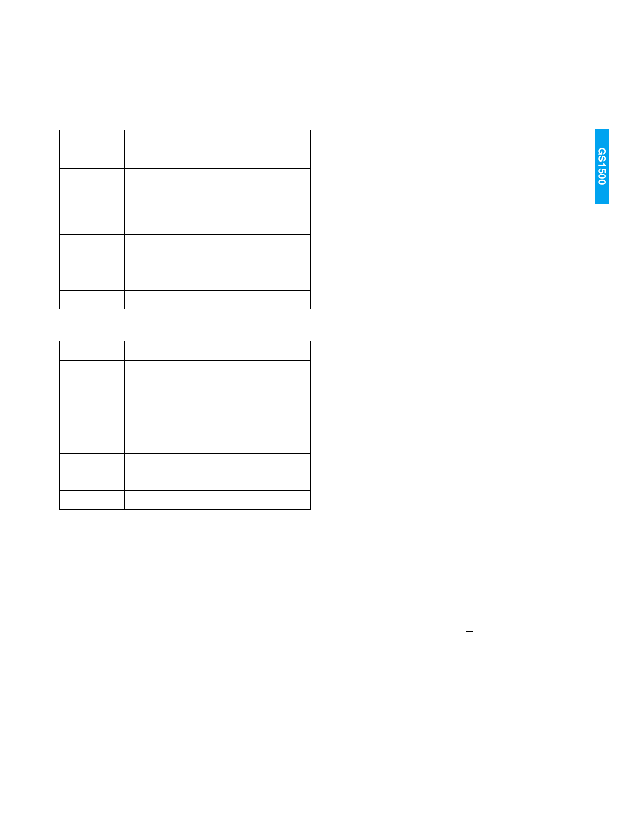
3. STANDARDS INDICATION
VD_STD[3:0] indicates the standard that the device has
detected. The states of VD_STD[3:0] are shown Tables 1
and 2.
TABLE 1. Progressive Scan Standards Indication (VD_STD[3]=0)
VD_STD[3:0]
DESCRIPTION
0000
720p (60 & 60/1.001Hz → L/M) [SMPTE296M]
0001
Reserved
0010
1080p (30 & 30/1.001Hz → G/H)
[SMPTE274M]
0011
Reserved
0100
1080p (25Hz → I) [SMPTE274M]
0101
Reserved
0110
1080p (24 & 24/1.001Hz → J/K) [SMPTE274M]
0111
Unknown Progressive with F = 0 always.
TABLE 2. Interlaced Standards Indication (VD_STD[3]=1)
VD_STD[3:0]
DESCRIPTION
1000
1080i (30 & 30/1.001Hz → D/E) [SMPTE274M]
1001
Reserved
1010
1080i (25Hz → F) [SMPTE274M]
1011
Reserved
1100
1080i (25Hz → C) [SMPTE295M]
1101
Reserved
1110
1035i (30 & 30/1.001Hz → A/B) [SMPTE260M]
1111
Unknown Interlaced with F switching 0/1
Note the following in the above Standards Indication Tables:
• SMPTE260M is 1125 lines/frame
• SMPTE274M is 1125 lines/frame
• SMPTE295M is 1250 lines/frame
• SMPTE296M is 750 lines/frame
See Table 3 for more details on the source format
parameters.
consecutive lines having identical timing are detected, this
new timing information is saved and the flywheel operation
is updated to this new timing. Mismatches between the HVF
information decoded from the data stream and that
indicated by the flywheel will trigger the EAV_ERR and
SAV_ERR signals as shown in Figure 3. HVF output timing is
shown in Figure 2.
5. AUTOMATIC SWITCH LINE LOCK HANDLING
The automatic switch line lock is based on the assumption
that switching occurs between video sources of the same
format. In other words, the switching of video sources
causes only the H signal to be out of alignment whereas V
and F signals remain in sync. Therefore, when in the
automatic switch line lock mode (FAST_LOCK transitions for
low to high), the flywheel positive H signal transition aligns
with the detected positive H signal transition. Timing for the
FAST_LOCK signal is shown in Figure 5.
6. FIFO
The device does not flag transmission errors which might
exist in the ANC data packages. The internal FIFO is 1024
words deep for each of LUMA and CHROMA channels. For
those formats where the HANC region is greater than 1024
words, the user must take steps to ensure the FIFO does
not overflow, otherwise data may be lost. The GS1500
provides status signals to indicate the current content level
of the internal FIFO buffers, as described in section 6.1.
6.1. FIFO Status Bits
The device provides status output signals FF_STA[2:0] that
indicate the state of the current content level of the internal
FIFO buffers. If the extracted ANC data have completely
filled the internal FIFO buffer, FF_STA[2:0] outputs 110.
When the internal FIFO is full, any attempt to write data into
the FIFO will cause the FIFO to overrun. The device flags
this overrun state by setting FF_STA[2:0]=111 and no more
data will be extracted from the video stream.
If all ANC data in the FIFO is accessed by the user through
the FIFO interface and the internal FIFO becomes empty,
then FF_STA[2:0] outputs 001. When the internal FIFO is
empty, any attempt to read data from the FIFO will cause
the FIFO to under run. The device flags this under run state
by setting FF_STA[2:0]=000.
When ANC_Y/C is high, FF_STA indicates the status of the
LUMA FIFO buffer. When ANC_Y/C is low, FF_STA indicates
the status of the CHROMA FIFO buffer.
4. FLY WHEEL OPERATION
The flywheel logic checks the incoming video data for valid
video lines. If the incoming data represents a valid line, the
flywheel remains in sync with the incoming data. If the
incoming data represents an invalid line, the flywheel uses
the stored timing information for the past valid line to
generate the output HVF timing signals. When three
The FIFO status flags must be up-to-date. Therefore, certain
FIFO status flags are synchronized with respect to R_CLK,
and others are synchronized with respect to PCLK_IN.
During a write cycle, status flags controlled by R_CLK
experience a three-cycle latency with respect to R_CLK.
During a read cycle, status flags controlled by PCLK_IN
experience a three-cycle latency with respect to PCLK_IN.
See Table 4 and Figures 6 to 15.
9
GENNUM CORPORATION
522 - 33 - 01
Share Link: 