NCP1560 데이터 시트보기 (PDF) - ON Semiconductor
부품명
상세내역
일치하는 목록
NCP1560 Datasheet PDF : 20 Pages
| |||
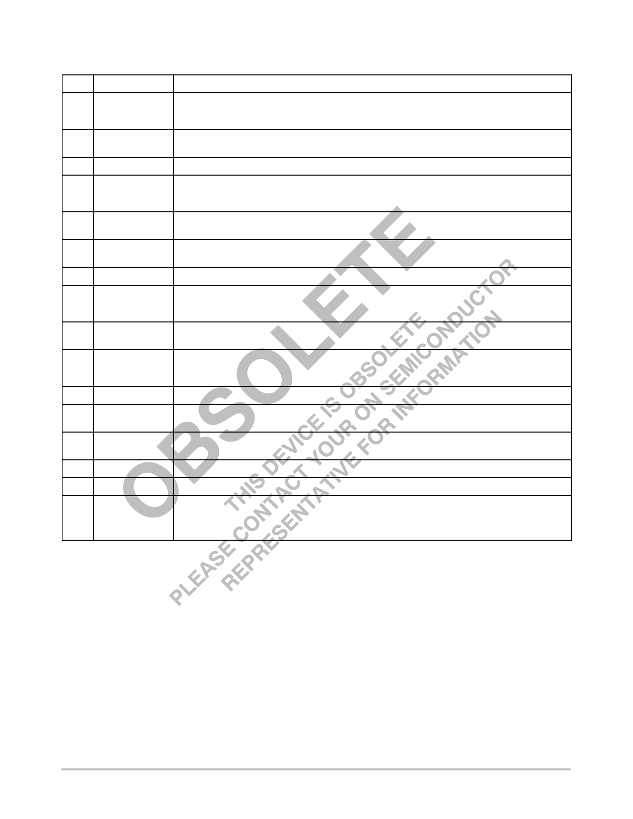
PIN DESCRIPTION
Pin
Name
1
Vin
2
UV/OV
3
NC
4
FF
5
CS
6
CSKIP
7
RT
8
DCMAX
9
SS
10
VEA
11
VREF
12
tD
13
OUT2
14
GND
15
OUT1
16
VAUX
NCP1560
Application Information
This pin is connected to the bulk DC input voltage supply. A constant current source supplies current from
this pin to the capacitor connected on the VAUX pin. The charge current is typically 13.8 mA. Input voltage
range is 21.5 V to 150 V.
Input supply voltage is scaled down and sampled by means of a resistor divider. The supply voltage must
be scaled down between 1.52 V and 3.61 V within the specified input voltage range.
Not Connected.
An external resistor between Vin and this pin adjusts the amplitude of the FF Ramp in proportion to Vin. By
varying the feedforward ramp amplitude in proportion to the input voltage, changes in loop bandwidth are
eliminated.
Over current sense input. If the CS voltage exceeds 0.48 V or 0.57 V, the converter enters the
Cycle−by−Cycle or Cycle Skip current limit mode, respectively.
The capacitor connected between this pin and ground sets the Cycle Skip period. A soft−start sequence
follows at the conclusion of the fault period.
A single external resistor between this pin and GND sets the oscillator fixed frequency.
An external resistor between this pin and GND sets the voltage on the Max DC Comparator inverting
input. The duty cycle is limited by comparing the voltage on the Max DC Comparator inverting input to the
Feedforward Ramp.
An internal 6.2 mA current source charges the external capacitor connected to this pin. The duty cycle is
limited during startup by comparing the voltage on this pin to the Oscillator Ramp.
The error signal from an external error amplifier is fed into this input and compared to the Feedforward
Ramp. A series diode and resistor offset the voltage on this pin before it is applied to the PWM
Comparator inverting input.
Precision 5.0 V reference output. Maximum output current is 6.0 mA.
An external resistor between VREF and this pin sets the overlap delay between OUT1 and OUT2
transitions.
Output of the PWM controller with leading and trailing edge overlap delay. OUT2 can be used to drive a
synchronous rectifier topology, an active clamp/reset switch, or both.
Control circuit ground.
Main output of the PWM controller.
Positive input supply voltage. This pin is connected to an external capacitor for energy storage. An
internal current supplies current from Vin to this pin. Once the voltage on VAUX reaches 11 V, the current
source turns OFF. It turns ON again once VAUX falls to 7.0 V. During normal operation, power is supplied
to the IC via this pin, by means of an auxiliary winding.
http://onsemi.com
4
Share Link: 