NCP1560 데이터 시트보기 (PDF) - ON Semiconductor
부품명
상세내역
일치하는 목록
NCP1560 Datasheet PDF : 20 Pages
| |||
NCP1560
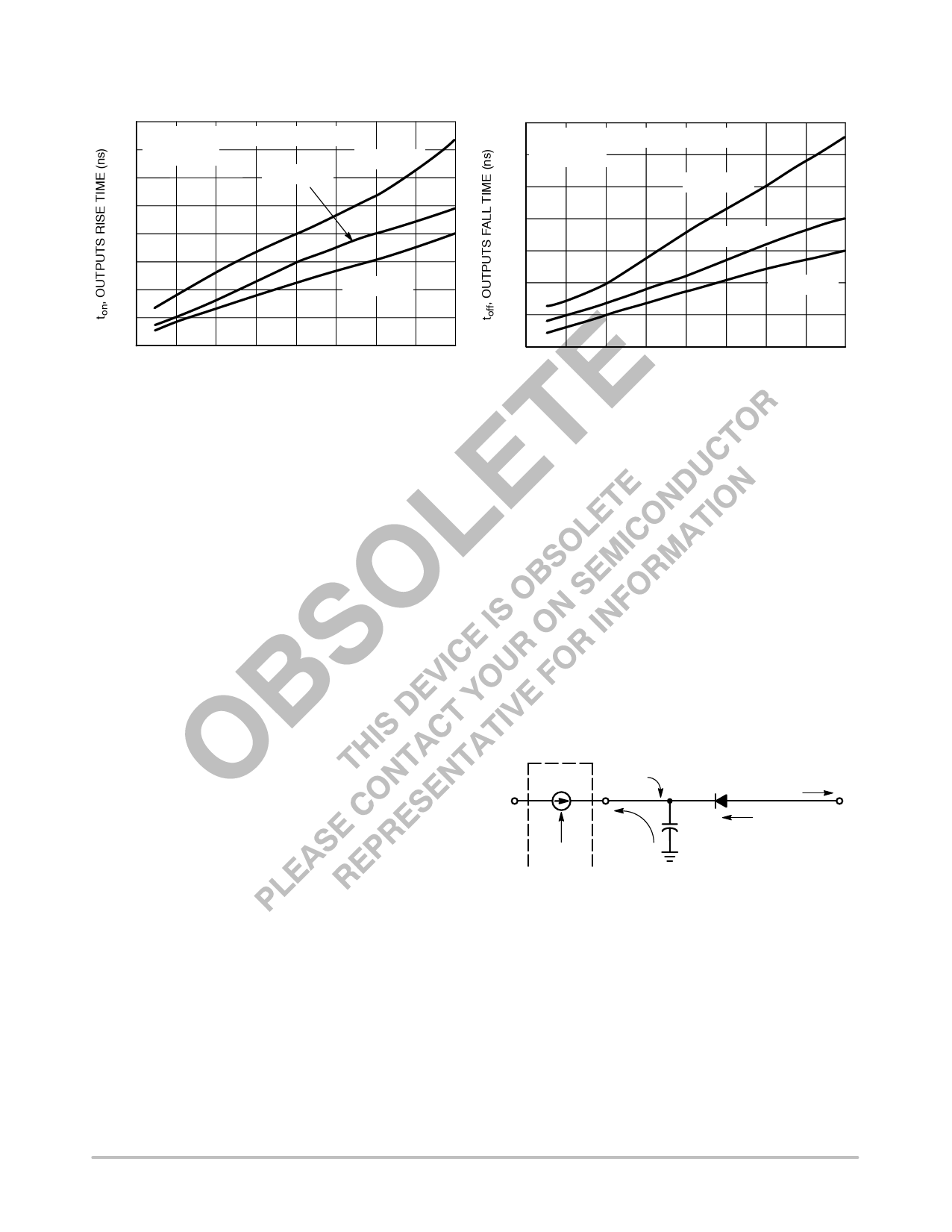
TYPICAL CHARACTERISTICS
80
Measured from 10% to 90% of VOH
70 VAUX = 12 V
60
TJ = 25°C
TJ = 125°C
50
40
30
20
TJ = −40°C
10
0
0 25 50 75 100 125 150 175 200
CL, LOAD CAPACITANCE (pF)
Figure 27. Outputs Rise Time versus Load
Capacitance
35
Measured from 90% to 10% of VOH
30 VAUX = 12 V
25
TJ = 125°C
20
TJ = 25°C
15
10
TJ = −40°C
5
0
0 25 50 75 100 125 150 175 200
CL, LOAD CAPACITANCE (pF)
Figure 28. Outputs Fall Time versus Load
Capacitance
DETAILED OPERATING DESCRIPTION
The NCP1560 PWM controller contains all the features
and flexibility needed for implementation of
Voltage−Mode Control in high performance DC−DC
converters. This device cost effectively reduces system part
count with the inclusion of a high voltage startup regulator.
The NCP1560 provides two control outputs. Output 1
controls the main switch of a forward or flyback topology.
Output 2 has an adjustable overlap delay, which can be used
to control an active clamp/reset switch, a synchronous
rectifier switch, or both. Other distinctive features include:
two mode overcurrent protection, line under/overvoltage
lockout, fast line feedforward, soft−start and a maximum
duty cycle limit. The Functional Block Diagram is shown in
Figure 2.
The features included in the NCP1560 provide all the
advantages of Current−Mode Control, fast line
feedforward, and cycle−by−cycle current limit. It eliminates
the disadvantages of low power jitter, slope compensation
and noise susceptibility.
High Voltage Startup Regulator
The NCP1560 contains an internal high voltage startup
regulator that eliminates the need for external startup
components. In addition, this regulator increases the
efficiency of the supply as it uses no power when in the
normal mode of operation, but instead uses power supplied
by an auxiliary winding.
The startup regulator consists of a constant current source
that supplies current from the input line voltage (Vin) to the
capacitor on the VAUX pin (CAUX). The startup current is
typically 13.8 mA. Once VAUX reaches 11 V, the startup
regulator turns OFF and the outputs are enabled. When VAUX
reaches 7.0 V, the outputs are disabled and the startup
regulator turns ON. This “7 − 11” mode of operation is known
as Dynamic Self Supply (DSS). The VAUX pin can be biased
externally above 7 V once the outputs are enabled to prevent
the startup regulator from turning ON. It is recommended to
bias the VAUX pin using an auxiliary supply generated out of
an auxiliary winding from the power transformer. An
independent voltage supply can also be used. However, if
VAUX is biased before the outputs are enabled or while a
fault is present, the One Shot Pulse Generator (Figure 2) will
not be enabled and the outputs will remain OFF.
As the DSS sources current to the VAUX pin, a diode should
be placed between CAUX and the auxiliary supply as shown
in Figure 29. This will allow the NCP1560 to charge CAUX
while preventing the startup regulator from sourcing current
into the auxiliary supply.
ISTART
Vin
ISTART
VAUX
Disable
IAUX
CAUX
To auxiliary supply
Isupply
Figure 29. Recommended VAUX Configuration
Power to the controller while operating in the self−bias or
DSS mode is provided by CAUX. Therefore, CAUX must be
sized such that a VAUX voltage greater than 7 V is
maintained while the outputs are switching and the
converter reaches regulation. Also, the VAUX discharge time
(from 11 V to 7 V) must be greater that the soft−start charge
period to assure the converter turns ON.
The startup circuit is rated at a maximum voltage of 150 V.
If the device operates in the DSS mode, power dissipation
should be controlled to avoid exceeding the maximum
power dissipation of the controller.
http://onsemi.com
12
Share Link: 