PCK2011 데이터 시트보기 (PDF) - Philips Electronics
부품명
상세내역
일치하는 목록
PCK2011 Datasheet PDF : 11 Pages
| |||
Philips Semiconductors
Direct Rambus™ Clock Generator
Preliminary specification
PCK2011
Power Management Modes
The DRCG device has three operating states: NORMAL, CLKSTOP
and POWERDOWN. In Normal mode, the clock source is on, and
the output is enabled. In CLKSTOP mode, the clock source is on,
but the output is disabled (STOPB deasserted). In Powerdown
mode, the device is powered down with the control signal PwrDnB
equal to 0. The control signals Mult0, Mult1, S0, S1 and S2 must be
stable before power is applied to the device, and can only be
changed in Power-down mode (PWRDNB=0).
Table 2. POWER MANAGEMENT MODES
MODE
NORMAL
CLKSTOP
POWERDOWN
PwrDnB
1
1
0
StopB
1
0
X
Clk
PACLK
VX, STOP
GND
ClkB
PACLKB
VX, STOP
GND
Upon applying power to the device, the device can enter any state,
depending on the settings of the control signals, PwrDnB and StopB.
The clock source output need not be glitch-free during state
transitions.
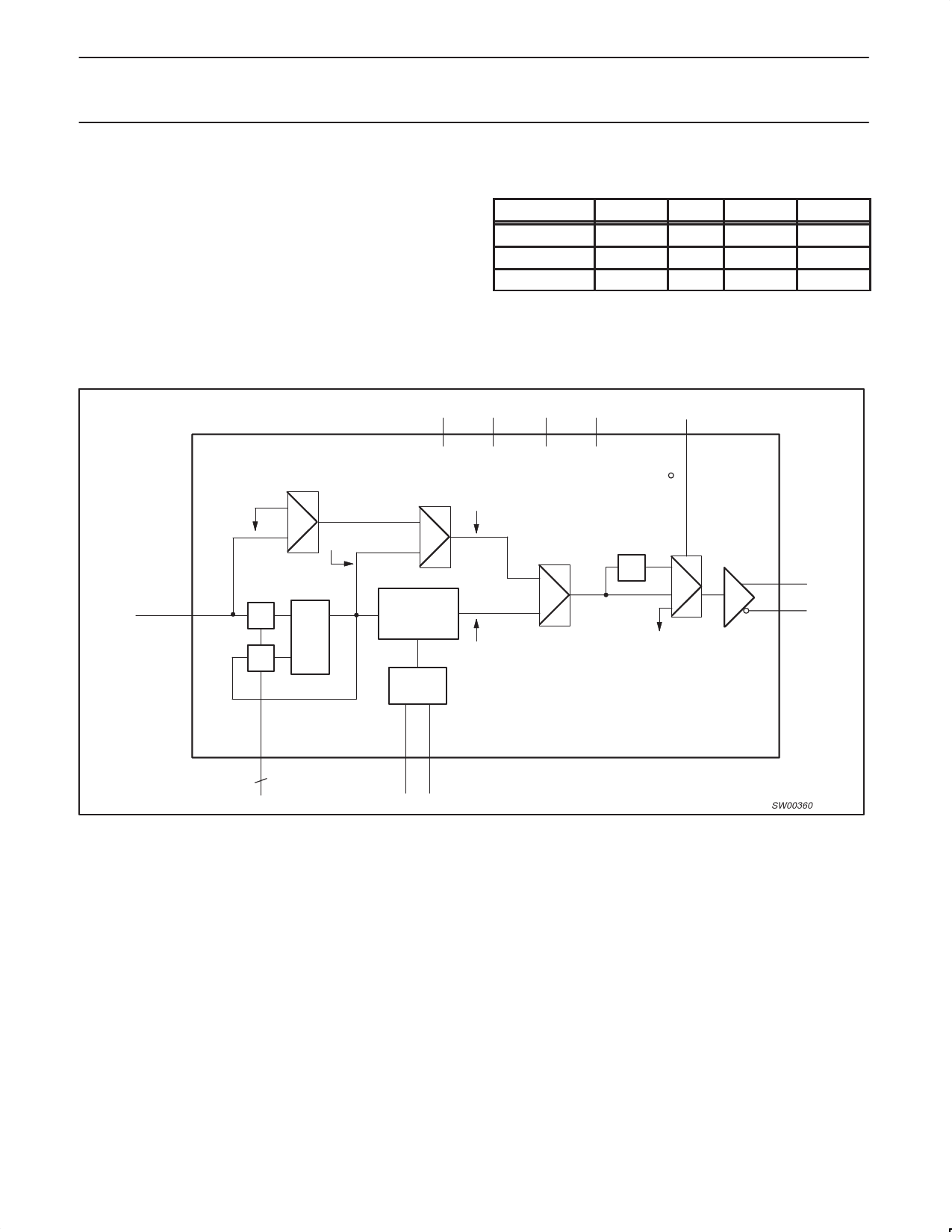
REFCLK
DRCG
TEST MUX
PLLCLK
B
PPL
A
PWRDNB S0
S1
BYPASS MUX
BYPCLK
PHASE
ALIGNER
PACLK
ΦD
S2
X
STOPB
CLK
CLKB
MULT
2
0
MULT
1
PCLKM
Figure 2. Direct Rambus Clock Generator Package
SYNCLKN
SW00360
1999 Jan 19
5
Share Link: 