PCK2011 데이터 시트보기 (PDF) - Philips Electronics
부품명
상세내역
일치하는 목록
PCK2011 Datasheet PDF : 11 Pages
| |||
Philips Semiconductors
Direct Rambus™ Clock Generator
Preliminary specification
PCK2011
Overview
The Direct Rambus Clock Generator (DRCG) provides the Channel
clock signals for a Direct Rambus memory subsystem. It includes
signals to synchronize the Direct Rambus Channel clock to an
external system clock. Contained in a 24-pin SSOP package, the
DRCG provides an off-the-shelf solution for a broad range of Direct
Rambus memory applications.
Features
• High Speed Clock Support
Provides a 400MHz differential clock source for Direct Rambus
memory systems for an 800MHz data transfer rate.
• Synchronization Flexibility
The DRCG includes signals to synchronize the clock domains of
the RambusR Channel with an external system or processor
clock.
• Power Management Support
The DRCG is able to turn off the Rambus Channel clock to
minimize power for mobile and other power-sensitive applications:
- In the “clock off” mode, the DRCG remains on while the output
is disabled, allowing fast transitions between the clock-off and
clock-on states. This mode could be used in conjunction with
the Nap mode of the RDRAMs and Rambus ASIC Cell (RAC).
- In the “power down” mode, the DRCG is completely powered
down for minimum power dissipation. This mode is used in
conjunction with the power down modes of the RDRAMs and
RAC.
• Supports Independent Channel Clocking
The DRCG supports systems that do not require synchronization
of the Rambus clock to another system clock.
• Works with Philips PCK2010 to support Intel CK98 Clock
Synthesizer/Driver specification.
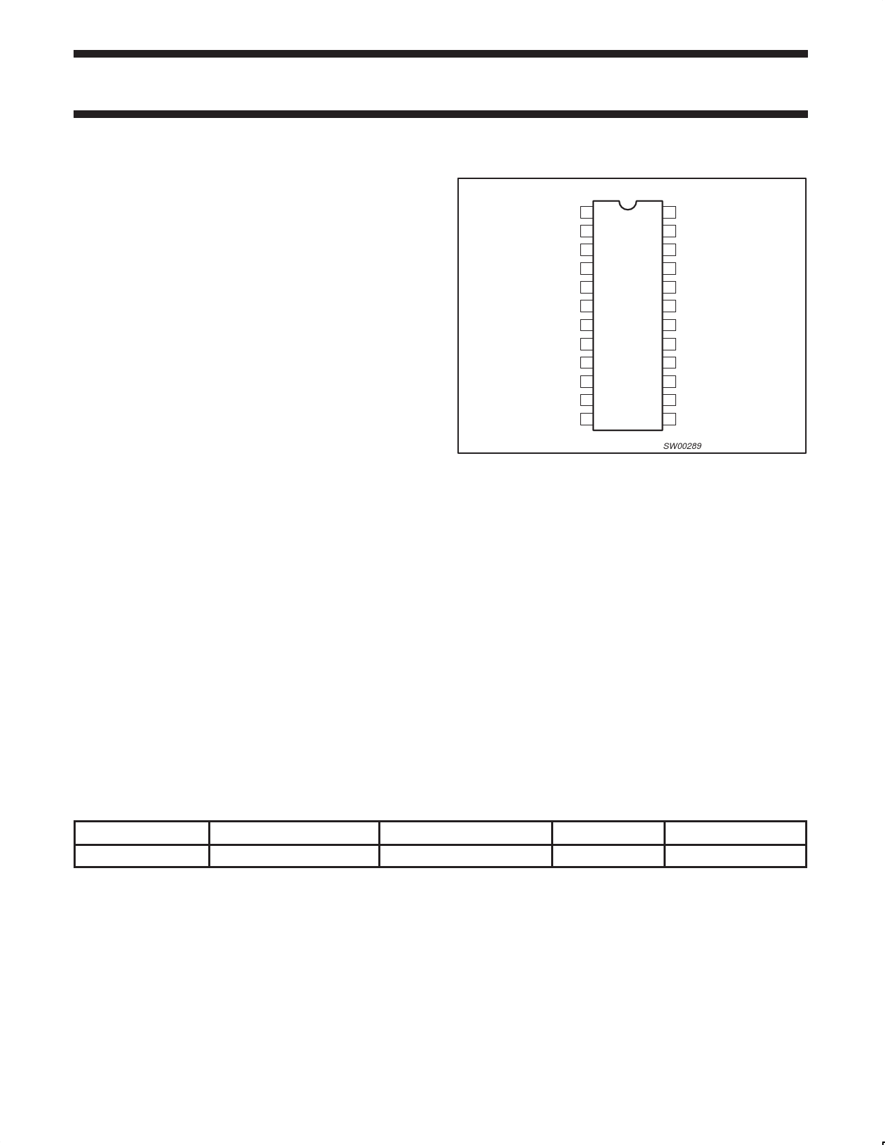
PIN CONFIGURATION
VDDLR 1
REFCLK 2
VDDP 3
GNDP 4
GNDl 5
PCLKM 6
SYNCLKN 7
GNDC 8
VDDC 9
VDDIPD 10
STOPB 11
PWRDNB 12
24 S0
23 S1
22 VDDO
21 GNDO
20 CLK
19 N/C
18 CLKB
17 GNDO
16 VDDO
15 MULT0
14 MULT1
13 S2
SW00289
Related Documentation
Direct Rambus RAC Overview
Direct Rambus Memory Controller Guide
Pin-outs
The DRCG is packaged in a 24-pin 150 mil SSOP. The pin
configuration shows the preliminary pin-out. Table 1 describes the
function and connection of each pin.
Example System Clock Configuration
Figure 2 shows the clocking configuration for an example Direct
Rambus subsystem. The configuration shows the interconnection of
the system clock source, the Direct Rambus Clock Generator
(DRCG), and the clock signals of a memory controller ASIC. The
ASIC contains the RAC, the Rambus Memory Controller protocol
engine (RMC), and logic to support synchronizing the Channel clock
with the controller clock. (This diagram represents the differential
clocks as a single Busclk wire.)
ORDERING INFORMATION
PACKAGES
TEMPERATURE RANGE
24-Pin Plastic SSOP
0°C to +70°C
OUTSIDE NORTH AMERICA NORTH AMERICA
PCK2011 DL
PCK2011 DL
DRAWING NUMBER
SOT340-1
1999 Jan 19
2
Share Link: 