VP603 데이터 시트보기 (PDF) - SANYO -> Panasonic
부품명
상세내역
일치하는 목록
VP603 Datasheet PDF : 8 Pages
| |||
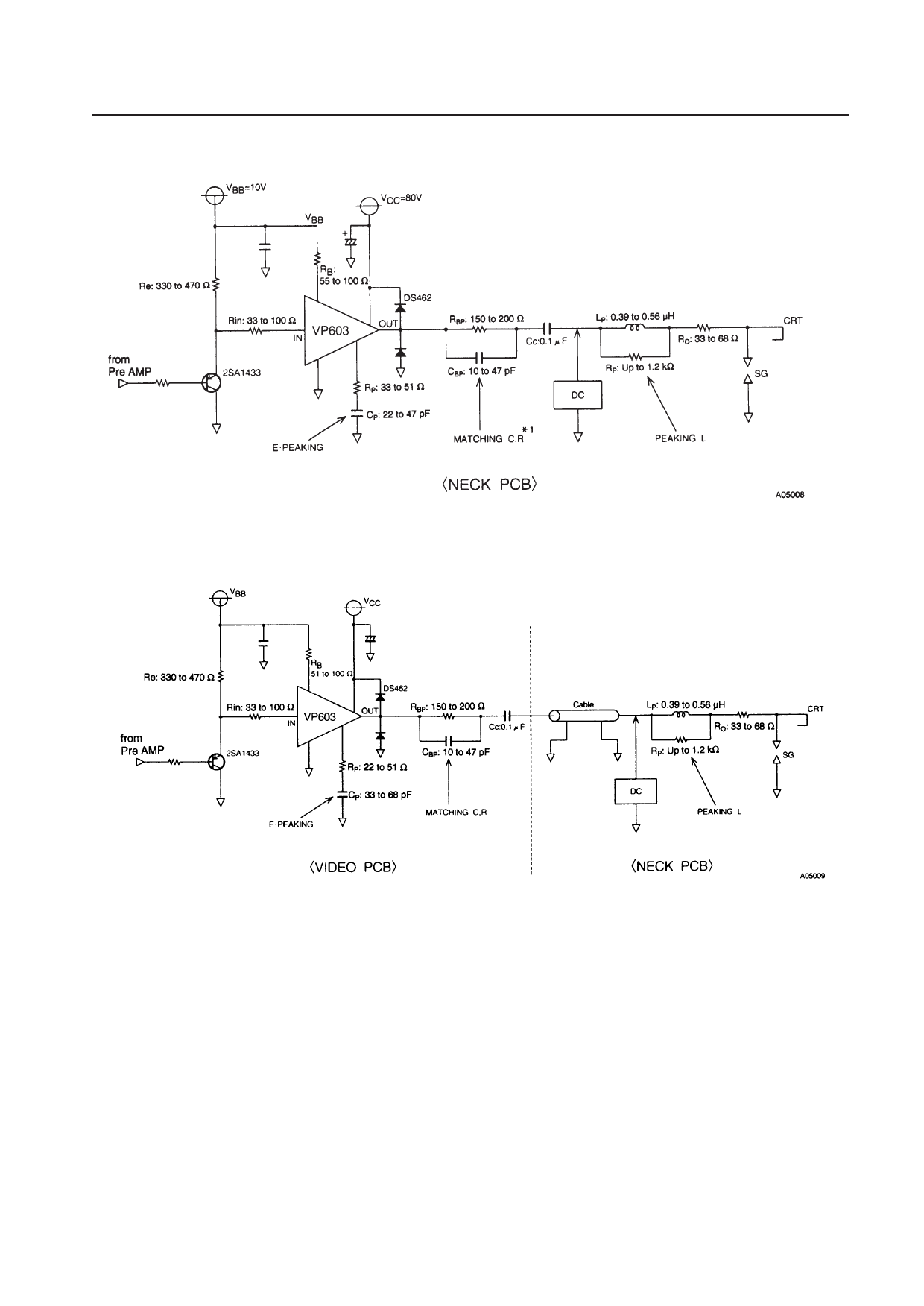
Sample Application Circuit
1. Mounting in the CRT neck
VP603
Note: * This RC matching circuit is provided to match the IC internal impedance with the output load impedance. When the IC is mounted in the CRT neck,
this circuit can be removed if the total CL (load capacitance) is under 10 pF.
2. Cable transmission (separate boards)
Mounting location for the C, G matching circuit
Add the RC matching circuit at a position as close as possible to the VP603 output pin.
Thermal Design for the VP603
Since the VP603 is a three-channel device, we first consider a single channel. The chip temperature of each transistor
during actual operation is determined using the following formula.
Tj = (Tri) = θj-c (Tri) × Pc (Tri) + ∆Tc + Ta [°C] .................................. (1)
θj-c (Tri): Thermal resistance of an individual transistor
Pc (Tri): Collector loss for an individual transistor
∆Tc: Case temperature rise
Ta:
Ambient temperature
No. 5542-4/8
Share Link: 