M62475FP 데이터 시트보기 (PDF) - MITSUBISHI ELECTRIC
부품명
상세내역
일치하는 목록
M62475FP Datasheet PDF : 19 Pages
| |||
MITSUBISHI SOUND PROCESSOR ICs
M62475FP
AUTOMATIC ADJUSTMENT CD PREAMPLIFIER SERVO CONTROLLER
AUTOMATIC ADJUSTMENT FUNCTION
The IC is capable of automatically adjusting the three places of
tracking balance, tracking gain and focus gain.
TRACKING BALANCE ADJUSTMENT
The input resistance of the I/V conversion amplifier connected to E
and F pickups and the 8-step adjustment resistance built in a
feedback resistance are switched for the adjustment. The
adjustment precision is approximately 3% by the step.
The automatic adjustment operation enters an oscillation signal
from the automatic adjustment signal generator of MCU into a
servo loop to forcibly make the beam cross the track. When this is
the case, the output voltage of I/V conversion amplifier is
integrated. If the E and F output signals are well balanced and are
the same, an error voltage is not generated in the output voltage
after this integration and a reference voltage is obtained. If they
are not balanced, a voltage of a DC component is generated. The
result of having compared this output voltage and the reference
voltage is converted into a logical level and is then output to the
monitor terminal. The MCU is used for control and the result is
judged. According to the result, the adjustment resistance of the
I/V conversion amplifier is sequentially switched step by step for
the adjustment in the direction of reversing the current logical
result. At the time when the result has been reversed, the error is
judged to be put within a one-step error and the adjustment is
complete.
TRACKING FOCUS GAIN ADJUSTMENT
The input resistance of the tracking focus error amplifier and the 8-
step adjustment resistance built in a feedback resistance are
switched for the adjustment. The adjustment precision is
approximately 1 dB by the step.
The adjustment operation enters an oscillation signal with the
output gain of -3 dB in a servo loop from the automatic adjustment
signal generator of MCU into a servo loop to forcibly generate a
gap in the track and focus. A waveform adjusted signal of the
generated tracking focus error signal and the MCU oscillation
signal are collated with each other with respect to the phase and is
then integrated to convert the phase difference into the voltage.
The result of having compared this output voltage and the
reference voltage is converted into a logical level and is then
output to the monitor terminal. The MCU is used for control and
the result is judged. According to the result, the input resistance of
the amplifier is sequentially switched step by step in feedback
resistance for the adjustment in the direction of reversing the
current logical result. At the time when the result has been
reversed, the error is judged to be put within a one-step error and
the adjustment is complete.
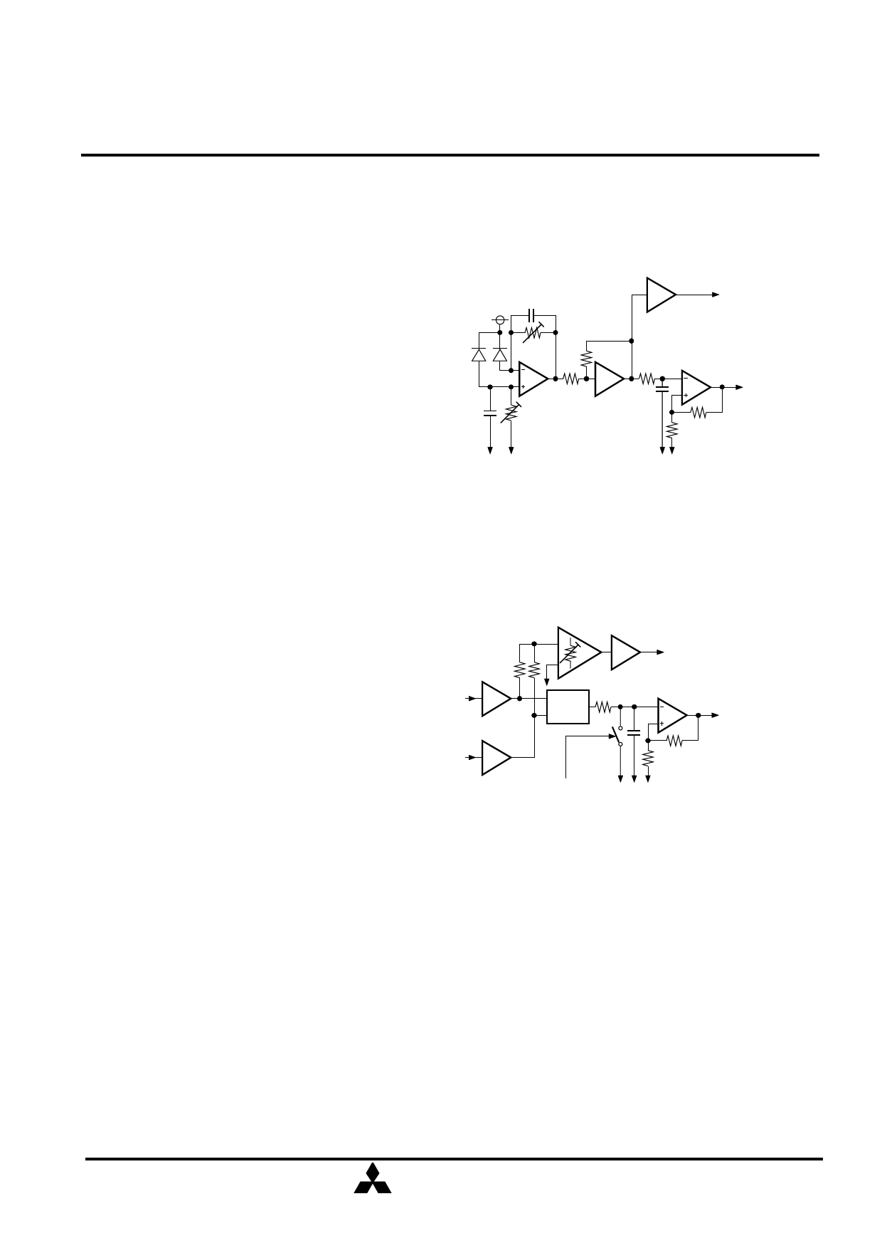
EQUIVALENT CIRCUIT (Tracking Balance)
TRACKING
ACTUATOR
PD
ADJUSTMENT
RESISTANCE
EF
I/V CONVERSION
AMPLIFIER
ADJUSTMENT
RESISTANCE
VOLTAGE
COMPARATOR
MONITOR
TERMINAL
(to MCU)
BIAS
VOLTAGE
BIAS
VOLTAGE
EQUIVALENT CIRCUIT (Tracking Focus Gain)
GAIN ADJUSTMENT
ERROR AMPLIFIER
EX-OR
TRACKING ACTUATOR
OR FOCUS ACTUATOR
VOLTAGE
COMPARISON
ACTUATOR
To DATA-OUT
MCU
MCU
BIAS
COMMAND VOLTAGE
LATCH SIGNAL
MITSUBISHI
ELECTRIC
( 7 / 19 )
Share Link: 