NCP1034(2008) 데이터 시트보기 (PDF) - ON Semiconductor
부품명
상세내역
일치하는 목록
NCP1034 Datasheet PDF : 23 Pages
| |||
NCP1034
Undervoltage Lock−out
There are four undervoltage lock−out circuits. Two of
them protect external high−side and low−side drivers, the
third ensures that the IC does not start until VCC is under a
set threshold. The last one can be programmed by the user.
It has a rising threshold at 1.25 V and a falling threshold at
1.15 V, and the user can define the undervoltage level by an
external resistor divider. If the voltage is not over the
threshold value, the device stops operating. The high−side
driver UVLO only stops switching the high−side MOSFET
Programmed falling and rising UVLO voltage can be
calculated by Equations 1 and 2:
ǒ Ǔ VUVLO,falling + 1.15 @
1 ) R4
R5
(eq. 1)
and
ǒ Ǔ VUVLO,rising + 1.25 @
1 ) R4
R5
(eq. 2)
Shutdown
The output voltage can be disabled by pulling the
SS/SD pin below 0.3 V. A small transistor can be used to pull
it down as shown in Figure 19. During this time, both
external MOSFETs are turned off. After the SS/SD pin is
released, the IC starts its operation with a soft−start
sequence.
SS/SD
SS/SD
Figure 19. Shutdown Interface
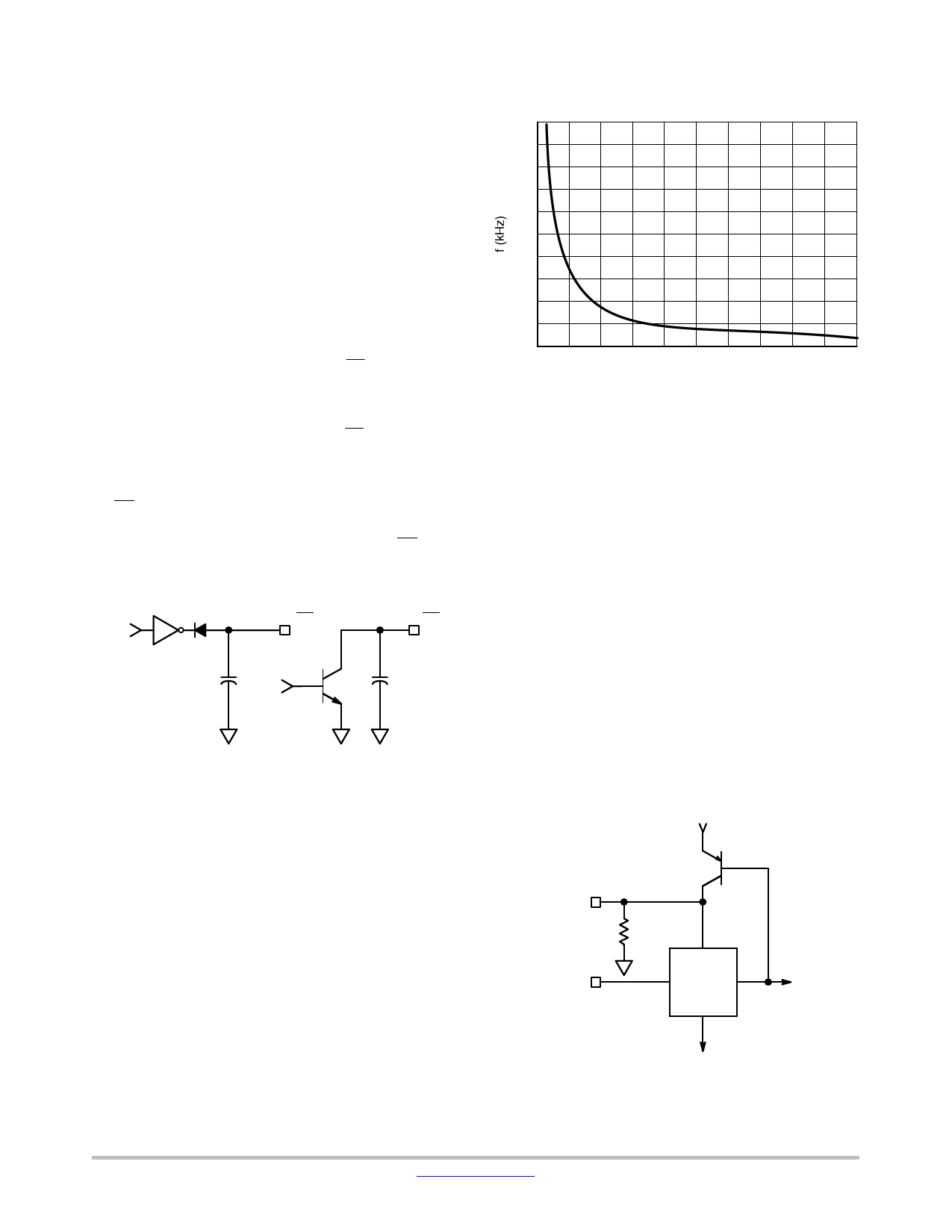
Operating Frequency Selection
The operating frequency is set by an external resistor
connected from the Rt Pin to ground. The value of this
resistor can be selected from Figure 20, which shows
switching frequency versus the timing resistor value.
500
450
400
350
300
250
200
150
100
50
0
0
50
100
150
200
250
Rt (kW)
Figure 20. Frequency Dependence of Rt Value
Frequency Synchronization
The NCP1034 can be synchronized to an external clock
signal. The input synchronization signal should be a TTL
logic level. The oscillator is synchronized to the rising edge
of the synchronizing signal. When synchronization is used,
the free running frequency must be set by the timing resistor
to a frequency at least 80% of the external synchronization
frequency.
The NCP1034 can also output synchronization pulses on
the Sync pin. Pulses are generated when the internal
oscillator ramp reaches the high threshold voltage. The
frequency of these pulses is set by an external Rt resistor. Up
to five NCP1034 controllers can be connected directly to the
SYNC pin, all of which are synchronized to the controller
with the highest frequency. The lowest frequency must be at
least 80% of the highest one.
The equivalent internal circuit of the Sync pin is shown in
Figure 21. Connection options (without synchronization,
external synchronization and master−slave
synchronization) are shown on Figure 22.
http://onsemi.com
11
Share Link: 