MP1518(2006) 데이터 시트보기 (PDF) - Monolithic Power Systems
부품명
상세내역
일치하는 목록
MP1518 Datasheet PDF : 9 Pages
| |||
TM
MP1518 – FIXED FREQUENCY WHITE LED DRIVER
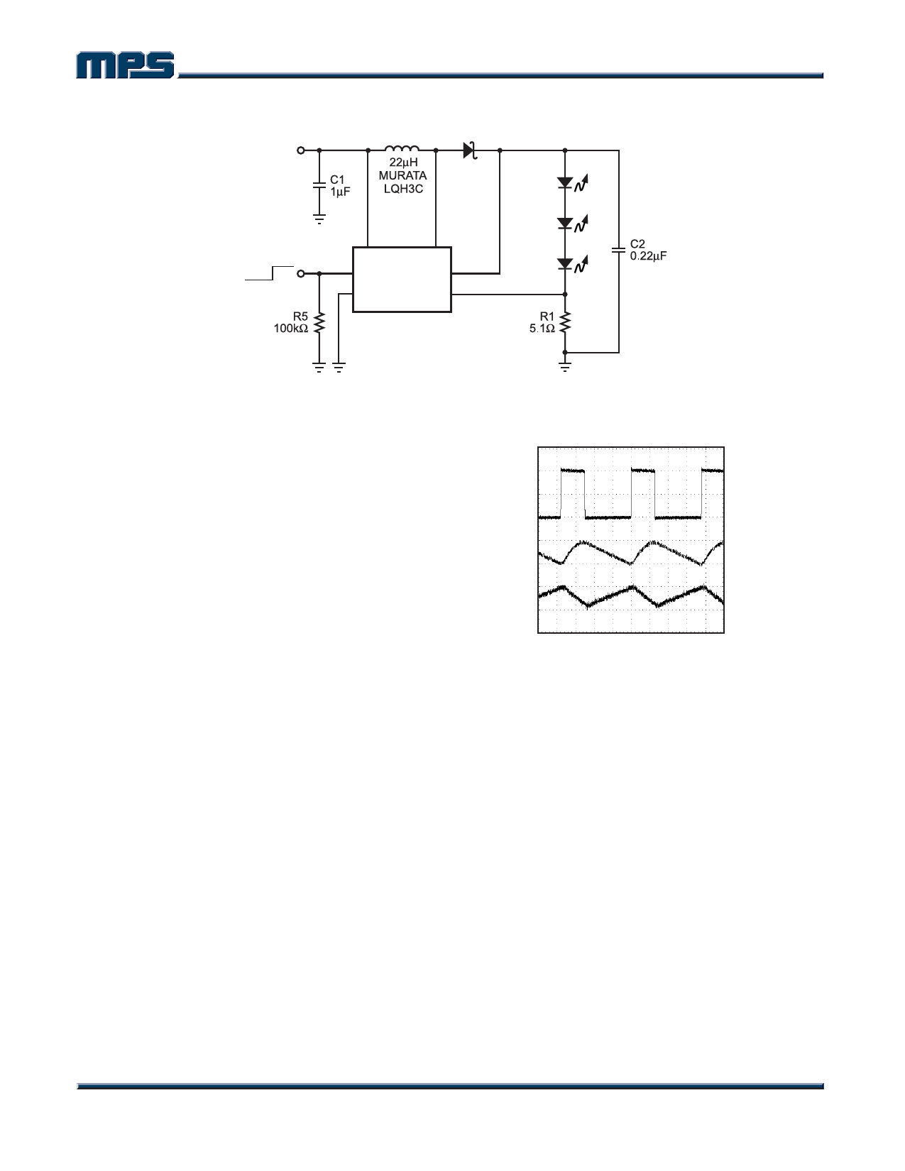
Startup Waveforms
VIN = 3.6V, 3 LEDs, 20mA
VEN
5V/div.
VOV
5V/div.
IIN
100mA/div.
Figure 4—Startup Waveforms
Figure 5 shows the dependence on current limit
versus duty cycle.
500
400
300
200
100
0
0 20 40 60 80 100
DUTY CYCLE (%)
Figure 5—Current Limit vs. Duty Cycle
Setting the LED Current
The LED current is controlled by the feedback
resistor, R1, in Figure 6. The current through
the LEDs is given by the equation 104mV/R1.
Table 2 shows the selection of resistors for a
given LED current.
Table 2—ILED vs. R1
ILED (mA)
1
5
10
15
20
R1 (Ω)
104
20.8
10.4
6.93
5.2
Analog and Digital Dimming
There are three different ways to control
dimming for the MP1518 during normal
operation. The first way uses a DC voltage to
control the feedback voltage. This can be seen
in Figure 6. As the DC voltage increases,
current starts flowing down R1, R2 and R3. The
loop will continue to regulate the feedback
voltage to 104mV. Thus the current has to
decrease through the LEDs by the same
amount of current as is being injected from the
DC voltage source. With a VDC from 0V to 2V,
the resistor values shown for R2 and R3 can
control the LED current from 0mA to 20mA.
VDC
MP1518
FB
LED1
LED2
LED3
Figure 6—Dimming Control Using a DC
Voltage
MP1518 Rev. 1.6
www.MonolithicPower.com
6
7/25/2006
MPS Proprietary Information. Unauthorized Photocopy and Duplication Prohibited.
© 2006 MPS. All Rights Reserved.
Share Link: 