MC80C86 데이터 시트보기 (PDF) - Intel
부품명
상세내역
일치하는 목록
MC80C86 Datasheet PDF : 19 Pages
| |||
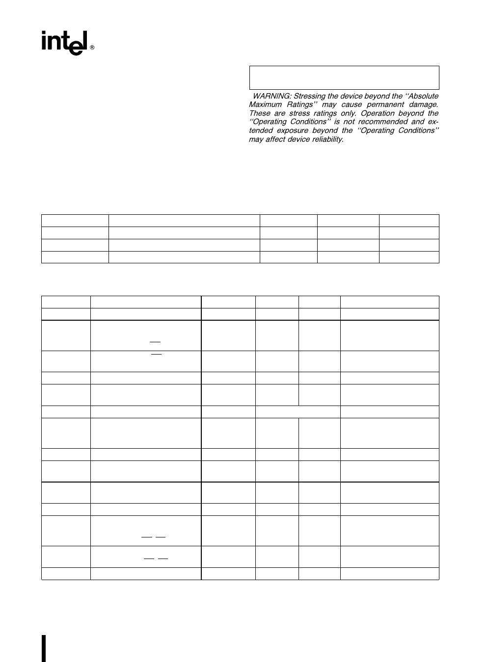
M80C86 M80C86-2
ABSOLUTE MAXIMUM RATINGS
Supply Voltage
(With respect to ground)
b0 5 to 8 0V
Input Voltage Applied
(w r t ground)
Output Voltage Applied
(w r t ground)
Power Dissipation
b2 0 to VCC a 0 5V
b0 5 to VCC a 0 5V
1 0W
Storage Temperature
b65 C to 150 C
Case Temperature Under Bias b55 C to a125 C
NOTICE This is a production data sheet The specifi-
cations are subject to change without notice
WARNING Stressing the device beyond the ‘‘Absolute
Maximum Ratings’’ may cause permanent damage
These are stress ratings only Operation beyond the
‘‘Operating Conditions’’ is not recommended and ex-
tended exposure beyond the ‘‘Operating Conditions’’
may affect device reliability
Operating Conditions
Symbol
Description
TC
Case Temperature (Instant On)
VCC
Digital Supply Voltage (M80C86)
VCC
Digital Supply Voltage (M80C86-2)
Min
b55
4 50
4 75
Max
a125
5 50
5 25
Units
C
V
V
D C CHARACTERISTICS (Over Specified Operating Conditions)
Symbol
Parameter
Min
Max
Units
VIL
Input Low Voltage
VIH
Input High Voltage
(All inputs except
clock and MN MX)
a0 8
V
22
V
VCH
Clock and MN MX
VCCb0 8
V
Input High Voltage
VOL
VOH
ICC
ICCS
Output Low Voltage
Output High Voltage
Power Supply Current
Standby Supply Current
30
VCCb0 4
04
V
V
10 mA MHz
500
mA
ILI
IBHL
IBHH
ILO
CIN
CIO
COUT
Input Leakage Current
Input Leakage Current
(Bus Hold Low) (Note 2)
Input Leakage Current
(Bus Hold High) (Note 3)
Output Leakage Current
Capacitance of Input Buffer
(All inputs except
AD0 – AD15 RQ GT)
Capacitance of I O Buffer
(AD0 – AD15 RQ GT)
Output Capacitance
40
b40
g1 0
mA
400
mA
b400
mA
g10
mA
10
pF
20
pF
15
pF
Comments
IOL e 2 5 mA
IOH e b2 5 mA
IOH e b100 mA
VIL e GND VIH e VCC
VIN e VCC or GND
Outputs Unloaded
CLK e GND or VCC
0V s VIN s VCC
VIN e 0 8V
VIN e 3 0V
VOUT e GND or VCC
(Note 1)
(Note 1)
(Note 1)
NOTES
1 Characterization conditions are a) Frequency e 1 MHz b) Unmeasured pins at GND c) VIN at a5 0V or GND
2 IBHL should be measured after lowering VIN to GND and then raising VIN to 0 8V on the following pins 2 – 16 34 – 39
3 IBHH should be measured after raising VIN to VCC and then lowering VIN to 3 0V on the following pins 2 – 16 26 – 32
34 –39
9
Share Link: 