CH1788ET 데이터 시트보기 (PDF) - Cermetek Microelectronics
부품명
상세내역
일치하는 목록
CH1788ET Datasheet PDF : 25 Pages
| |||
Cermetek Microelectronics, Inc.
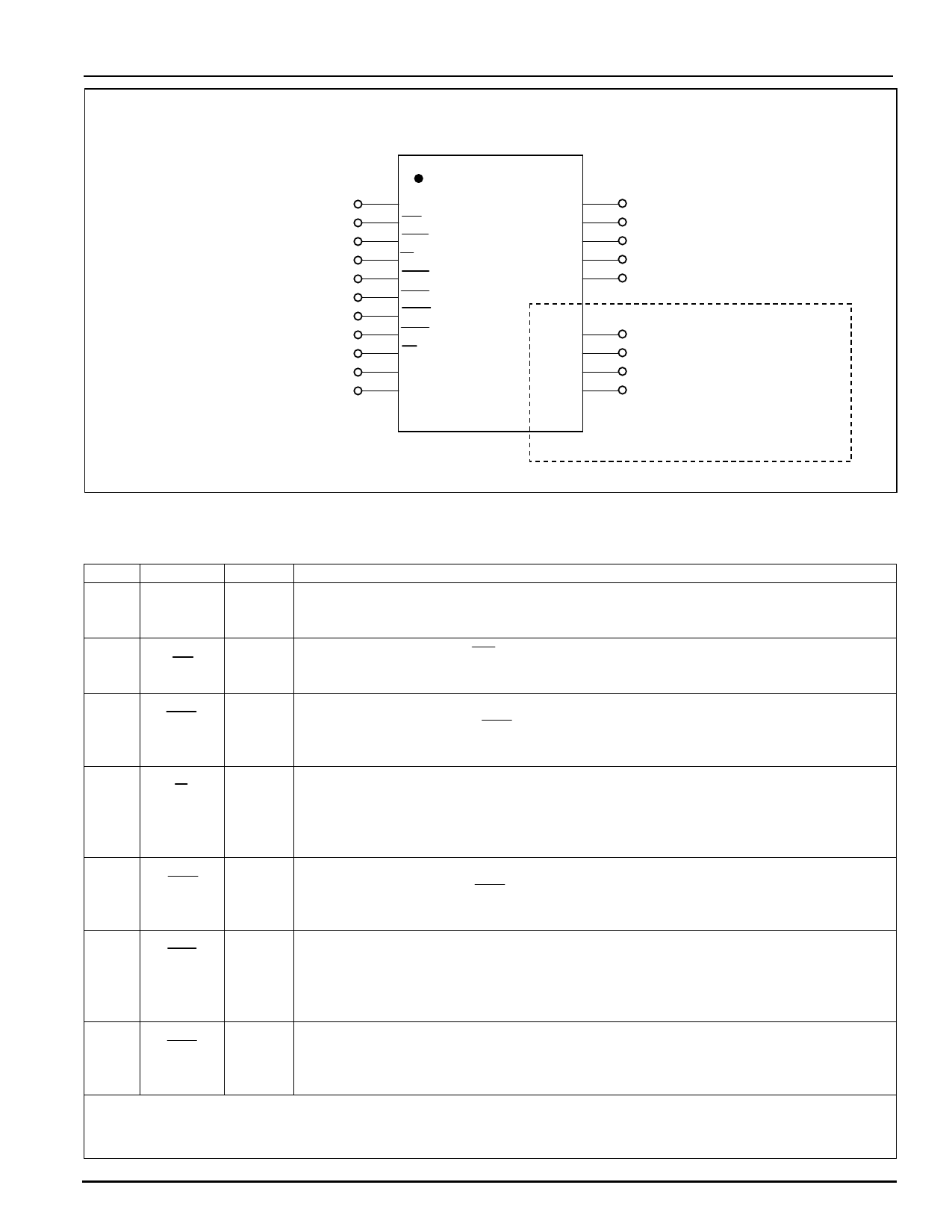
CH1788 Surface Mount PLCC 2400bps Modem
CH1788
Used for LIU/911/General IO
Used for LIU/911/Audio Control
DTE Signal
DTE Signal
DTE Signal
DTE Signal
DTE Signal
DTE Signal
Used for LIU/911/Detection
DTE Signal
Optional High Reset Input
1
2
A1
3
OH
RTS
4
5
6
7
RI
CTS
DSR
DCD
8
9
DTR
A2
10 TXD
11 RST
Top View
RXD
22
21
GND
VCC
S2
20
19
S1 18
V-
V+
TIP
15
14
13
RING 12
DTE Signal
Power Input +5V
Optional S1/S2 Audio
Monitor/Tone/Voice
V+/V- Optional
CID Input
Telephone Line
Input
High Voltage Section
Figure 2. CH1788 Pin Configuration. See Table 2 for detailed Pin Descriptions.
PIN NAME TYPE
Table 2. CH1788 Pin Descriptions.
FUNCTION
1
A1
O
Optional Input. Active high. Used when implementing the 911 Priority Pick-Up
circuit or the Line In Use circuit.
2
OH
O
Off-Hook. Active low. OH Indicates when the CH1788 is Off-Hook. Used in Line
In Use, 911 Priority Pick-Up applications and for Audio Control.
3
RTS
I
Request To Send. Active low. Used for optional flow control. Used in conjunction
with the Clear to Send (CTS) pin as a handshaking signal. See the details of
register S90.
4
RI
O
Ring Indication. Active low. For each occurrence of a valid ring signal, this pin will
pulse low for 70 ms. This output signal follows the frequency of the ringing signal
and is typically in the 20 to 40 Hz range with a cadence of 2 seconds on with 4
seconds off.
5
CTS
O
Clear to send. Active low. Used for optional flow control. Used in conjunction with
the Request To Send (RTS) pin as a handshaking signal. See the details of
register S90.
6
DSR
O
Data Set Ready. Active low. A low indicates that handshaking with the remote
modem is in progress and/or the carrier of the remote modem has been detected
and a valid connection is imminent as measured by DCD being active. This feature
is enabled with the N command.
7
DCD
O
Data Carrier Detect. Active low. This output must be enabled with the C
command. When enabled, it will become active when both the originated and
answering modems are connected and a data carrier has been detected.
NOTE: 1. All unused pins should be left unconnected when not required in a specific application,
unless specifically directed otherwise.
2. See DC characteristics before attempting to drive an LED directly from the output of any pin.
2003 Cermetek Microelectronics, Inc.
Page 5
Document No. 607-0018 Revision A2 (07/03)
Share Link: 