IDT723644 데이터 시트보기 (PDF) - Integrated Device Technology
부품명
상세내역
일치하는 목록
IDT723644
Integrated Device Technology

IDT723644 Datasheet PDF : 35 Pages
| |||
IDT723624/723634/723644 CMOS SyncBiFIFO™ WITH BUS-MATCHING
256 x 36 x 2, 512 x 36 x 2, 1,024 x 36 x 2
COMMERCIAL TEMPERATURE RANGE
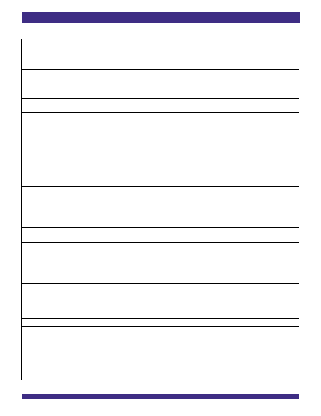
PIN DESCRIPTIONS
Symbol
Name
I/O
Description
A0-A35
AEA
AEB
AFA
AFB
Port A Data I/O 36-bit bidirectional data port for side A.
Port A Almost- O Programmable Almost-Empty flag synchronized to CLKA. It is LOW when the number of words in FIFO2 is less
Empty Flag
than or equal to the value in the Almost-Empty A Offset register, X2.
Port B Almost- O Programmable Almost-Empty flag synchronized to CLKB. It is LOW when the number of words in FIFO1 is less
Empty Flag
than or equal to the value in the Almost-Empty B Offset register, X1.
Port A Almost- O Programmable Almost-Full flag synchronized to CLKA. It is LOW when the number of empty locations in FIFO1
Full Flag
is less than or equal to the value in the Almost-Full A Offset register, Y1.
Port B Almost- O Programmable Almost-Full flag synchronized to CLKB. It is LOW when the number of empty locations in FIFO2
Full Flag
FIFO2 is less than or equal to the value in the Almost-Full B Offset register, Y2.
B0-B35
BE/FWFT
Port A Data
Big-Endian/
First Word
Fall Through
Select
I/O 36-bit bidirectional data port for side B.
I This is a dual purpose pin. During Master Reset, a HIGH on BE will select Big Endian operation. In this case,
depending on the bus size, the most significant byte or word on Port A is read from Port B first (A-to-B data
flow) or written to Port B first (B-to-A data flow). A LOW on BE will select Little-Endian operation. In this case,
the least significant byte or word on Port A is read from Port B first (for A-to-B data flow) or written to Port B first
(B-to-A data flow). After Master Reset, this pin selects the timing mode. A HIGH on FWFT selects IDT
Standard mode, a LOW selects First Word Fall Through mode. Once the timing mode has been
selected, the level on FWFT must be static throughout device operation.
BM(1)
Bus-Match
I A HIGH on this pin enables either byte or word bus width on Port B, depending on the state of SIZE. A LOW
Select
selects long word operation. BM works with SIZE and BE to select the bus size and endian arrangement for
(Port B)
Port B. The level of BM must be static throughout device operation.
CLKA
Port A Clock
I CLKA is a continuous clock that synchronizes all data transfers through Port A and can be asynchronous or
coincident to CLKB. FFA/IRA, EFA/ORA, AFA, and AEA are all synchronized to the LOW-to-HIGH transition of
CLKA.
CLKB
Port B Clock
I CLKB is a continuous clock that synchronizes all data transfers through Port B and can be asynchronous or
coincident to CLKA. FFB/IRB, EFB/ORB, AFB, and AEB are synchronized to the LOW-to-HIGH transition of
CLKB.
CSA
Port A Chip
I CSA must be LOW to enable to LOW-to-HIGH transition of CLKA to read or write on Port A. The A0-A35
Select
outputs are in the high-impedance state when CSA is HIGH.
CSB
Port B Chip
I CSB must be LOW to enable a LOW-to-HIGH transition of CLKB to read or write on Port B. The B0-B35
Select
outputs are in the high-impedance state when CSB is HIGH.
EFA/ORA Port A Empty/ O This is a dual function pin. In the IDT Standard mode, the EFA function is selected. EFA indicates whether or
Output Ready
not the FIFO2 memory is empty. In the FWFT mode, the ORA function is selected. ORA indicates the presence
Flag
of valid data on A0-A35 outputs, available for reading. EFA/ORA is synchronized to the LOW-to-HIGH
transition of CLKA.
EFB/ORB Port B Empty/ O This is a dual function pin. In the IDT Standard mode, the EFB function is selected. EFB indicates whether or
Output Ready
not the FIFO1 memory is empty. In the FWFT mode, the ORB function is selected. ORB indicates the presence
Flag
of valid data on the B0-B35 outputs, available for reading. EFB/ORB is synchronized to the LOW-to-HIGH transition
of CLKB.
ENA
Port A Enable I ENA must be HIGH to enable a LOW-to-HIGH transition of CLKA to read or write data on Port A.
ENB
Port B Enable I ENB must be HIGH to enable a LOW-to-HIGH transition of CLKB to read or write data on Port B.
FFA/IRA
Port A Full/
Input Read
Flag
O This is a dual function pin. In the IDT Standard mode, the FFA function is selected. FFA indicates whether or
not the FIFO1 memory is full. In the FWFT mode, the IRA function is selected. IRA indicates whether or not
there is space available for writing to the FIFO1 memory. FFA/IRA is synchronized to the LOW-to-HIGH
transition of CLKA.
FFB/IRB
Port B Full/
Input Ready
Flag
O This is a dual function pin. In the IDT Standard mode, the FFB function is selected. FFB indicates whether or
not the FIFO2 memory is full. In the FWFT mode, the IRB function is selected. IRB indicates whether or not
there is space available for writing to the FIFO memory. FFB/IRB is synchronized to the LOW-to-HIGH transition
of CLKB.
4
Share Link: