SY100E445 데이터 시트보기 (PDF) - Micrel
부품명
상세내역
일치하는 목록
SY100E445 Datasheet PDF : 8 Pages
| |||
Micrel, Inc.
LAOPGPLICICDAITAIGORNASMINFORMATION
The SY10/100E are integrated 1:4 serial-to-parallel
converters. The chips are designed to work with the
E446 devices to provide both transmission and receiving
of a high-speed serial data path. The E445, under special
input conditions, can convert up to a 2.5Gb/s NRZ data
stream into 4-bit parallel data. The device also provides
a divide-by-four clock output to be used to synchronize
the parallel data with the rest of the system.
The E445 features multiplexed dual serial inputs to
provide test loop capability when used in conjunction
with the E446. Figure 1 illustrates the loop test
architecture. The architecture allows for the electrical
testing of the link without requiring actual transmission
over the serial data path medium. The SINA serial input
of the E445 has an extra buffer delay and, thus, should
be used as the loop back serial input.
Parallel
Data
SOUT
SOUT
To Serial
Medium
SY10E445
SY100E445
Clock
Clock
Serial Input
Data
E445a
SIN
SOUT
SIN
SOUT
Q3 Q2 Q1 Q0
E445b
SIN
SIN
Q3 Q2 Q1 Q0
Q7 Q6 Q5 Q4
Q3 Q2 Q1 Q0
Parallel Output Data
Clock
100ps
Tpd CLK
to SOUT
800ps
1050ps
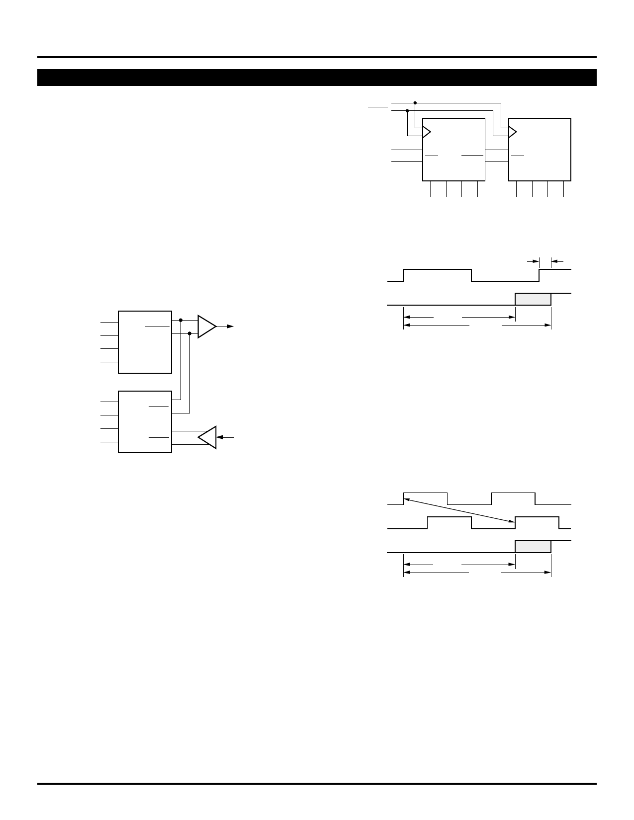
Figure 2. Cascaded 1:8 Converter Architecture
Parallel
Data
SINA
SINA
SINB
SINB
From Serial
Medium
Figure 1. Loop Test Architecture
clock-to-serial-out would potentially cause a serial bit to
be swallowed (Figure 3). With a minimum delay of 800ps
on this output, the clock for the lower order E445 cannot
be delayed more than 800ps relative to the clock of the
first E445 without potentially missing a bit of information.
Because the set-up time on the serial input pin is
negative, coincident excursions on the data and clock
inputs of the E445 will result in correct operation.
The E445 features a differential serial output and a
divide-by-8 clock output to facilitate the cascading of two
devices to build a 1:8 demultiplexer. Figure 2 illustrates
the architecture of a 1:8 demultiplexer using two E445s.
The timing diagram for this configuration can be found
on the following page. Notice the serial outputs (SOUT)
of the lower order converter feed the serial inputs of the
higher order device. This feedthrough of the serial inputs
bounds the upper end of the frequency of operation. The
clock-to-serial output propagation delay, plus the set-up
time of the serial input pins, must fit into a single clock
period for the cascade architecture to function properly.
Using the worst case values for these two parameters
from the data sheet, tPD CLK to SOUT = 1150ps or a
clock frequency of 950MHz.
The clock frequency is significantly lower than that of
a single converter. To increase this frequency, some
games can be played with the clock input of the higher
order E445. By delaying the clock feeding the second
E445 relative to the clock of the first E445, the frequency
of operation can be increased. The delay between the
two clocks can be increased until the minimum delay of
Clock a
Clock b
Tpd CLK
to SOUT
800ps
1050ps
Figure 3. Cascade Frequency Limitation
Perhaps the easiest way to delay the second clock
relative to the first is to take advantage of the differential
clock inputs of the E445. By connecting the clock for the
second E445 to the complimentary clock input pin, the
device will clock a half a clock period after the first E445
(Figure 4). Utilizing this simple technique will raise the
potential conversion frequency up to 1.5GHz. The divide-
by-eight clock of the second E445 should be used to
synchronize the parallel data to the rest of the system as
the parallel data of the two E445s will no longer be
synchronized. This skew problem between the outputs
can be worked around as the parallel information will be
static for eight more clock pulses.
M9999-032206
hbwhelp@micrel.com or (408) 955-1690
5
Share Link: 