FARM 데이터 시트보기 (PDF) - Vicor
부품명
상세내역
일치하는 목록
FARM Datasheet PDF : 12 Pages
| |||
Application Note (continued)
PRELIMINARY
80
75
70
65
60
55
50
45
40
25
15
30
50
Output Voltage
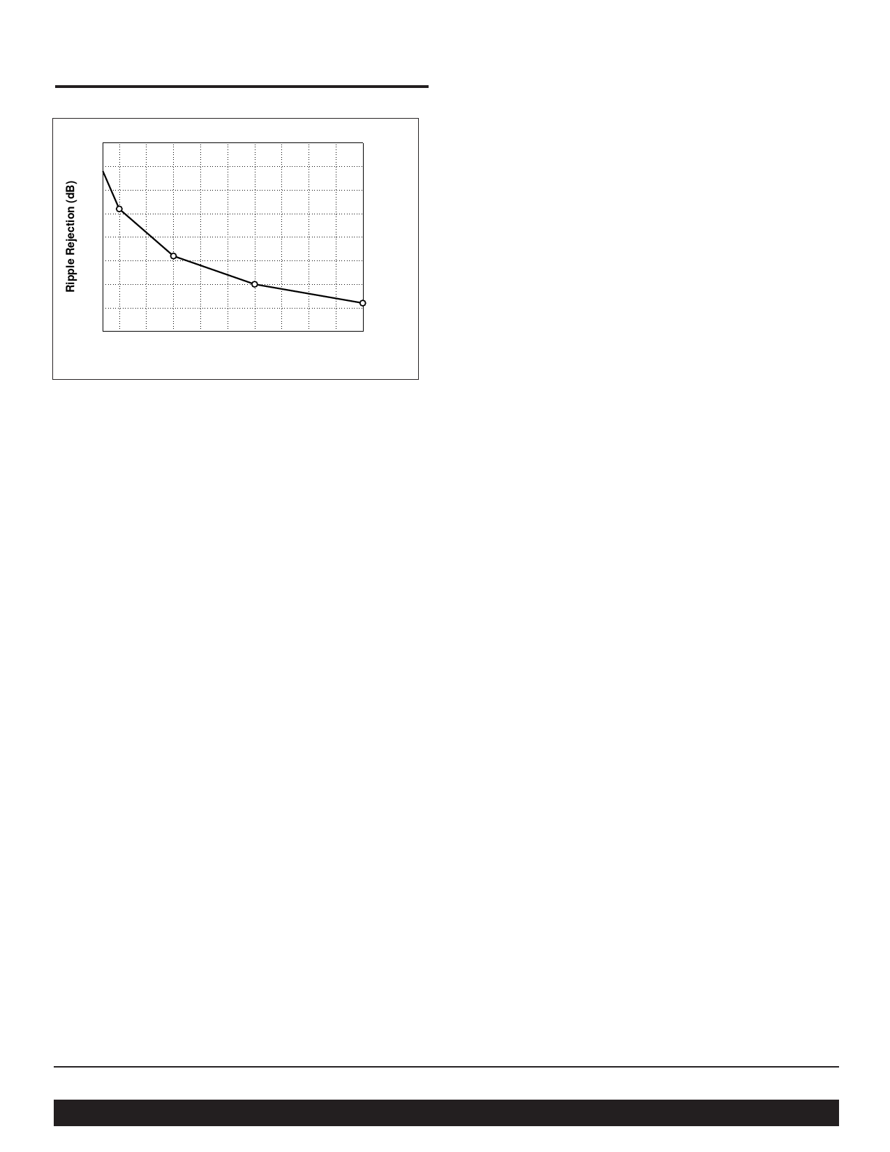
Figure 17—Converter ripple rejection vs. output voltage
Another consideration in hold-up capacitor selection is their
ripple current rating. The capacitors’ rating must be higher
than the maximum operating ripple current. The approximate
operating ripple current (rms) is given by:
I rms = 2P/Vac
(7)
Where: P = total output power
Vac = operating line voltage
Calculated values of bus capacitance for various hold-up
time, ride-through time, and ripple voltage requirements are
given as a function of operating power level in Figures 14, 15,
and 16, respectively.
Example
In this example, the output required from the DC-DC converter
at the point of load is 12Vdc at 320W. Therefore, the output
power from the FARM would be 375W (assuming a converter
efficiency of 85%). The desired hold-up time is 9 ms over an
input range of 90 to 264Vac.
Determining Required Capacitance for Power Fail
Warning. Figure 14 is used to determine capacitance for a
given power fail warning time and power level, and shows
that the total bus capacitance must be at least 820 µF. Since
two capacitors are used in series, each capacitor must be at
least 1,640 µF. Note that warning time is not dependent on
line voltage. A hold-up capacitor calculator is available on the
Vicor website, at vicorpower.com.
Determining Ride-through Time. Figure 15 illustrates ride-
through time as a function of line voltage and output power,
and shows that at a nominal line of 90Vac, ride-through would
be 68 ms. Ride-through time is a function of line voltage.
Determining Ripple Voltage on the Hold-up Capacitors.
Figure 16 is used to determine ripple voltage as a function of
operating power and bus capacitance, and shows that the
ripple voltage across the hold-up capacitors will be 12V p-p.
Determining the Ripple on the Output of the
DC-DC Converter. Figure 17 is used to determine the ripple
rejection of the DC-DC converter and indicates a ripple
rejection of approximately 60 dB for a 12V output. Since the
ripple on the bus voltage is 12Vac and the ripple rejection of
the converter is 60 dB, the output ripple of the converter due
to ripple on its input (primarily 120 Hz) will be 12mV p-p.
Note that 2nd Generation converters have greater ripple
rejection then either VI-200s or VI-J00s.
For more information about designing an autoranging
AC input power supply using the FARM and Vicor DC-DC
converter modules, contact Vicor Applications Engineering at
the nearest Vicor Technical Support Center, or send E-mail to
apps@vicr.com.
•••
Vicor Corp. Tel: 800-735-6200, 978-470-2900 Fax: 978-475-6715
FARM, Filter/Autoranging Rectifier Module
Set your site on VICOR at www.vicorpower.com
Rev. 4.7
Page 9 of 12
Share Link: 