FARM 데이터 시트보기 (PDF) - Vicor
부품명
상세내역
일치하는 목록
FARM Datasheet PDF : 12 Pages
| |||
Application Note (continued)
PRELIMINARY
N
EMI GND
+
15Vdc
B OK
150k
ST
N/C
EN
Micro-
controller
L
–
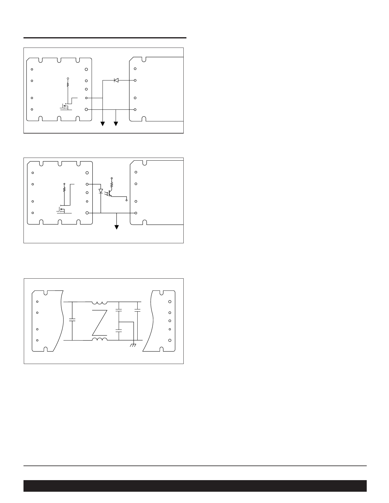
Figure 10—Enable (EN) function
+In
PC (Gate In)
Vicor DC-DC
Converter
PR (Gate Out)
–In
N
+
15 Vdc
EMI GND
27kΩ
B OK
ST
N/C
EN
Micro-
controller
L
–
+5 Vdc
Secondary
referenced
+In
PC (Gate In)
Vicor DC-DC
Converter
PR (Gate Out)
–In
Optocoupler DI pkg. 26106
Optocoupler SM pkg. 26109
Figure 11—Bus OK (BOK) isolated power status indicator
N
EMI GND
N/C
L
330µH
L1
.47µF
4.7nF
4.7nF
+
.099µF
B OK
ST
EN
–
Figure 12—Internal filter
Bus-OK (BOK) Pin. (see Fig. 11) The Bus-OK pin is
intended to provide early-warning power fail information and
is also referenced to the negative output pin.
Caution: There is no input to output isolation in the FARM. It is
necessary to monitor Bus-OK via an optoisolator if it is to be
used on the secondary (output) side of the converters. A line
isolation transformation should be used when performing scope
measurements. Scope probes should never be applied
simultaneously to the input and output as this will destroy the unit.
Filter. (see Fig. 12) An integral input filter consists of a
common mode choke and Y rated capacitors (line-ground)
plus two X rated capacitors (line-line). This filter
configuration provides common mode and differential mode
insertion loss in the frequency range between 100kHz and
30MHz as illustrated in Figure 6.
Hold-up Capacitors. Hold-up capacitor values should be
determined according to output bus voltage ripple, power fail
hold-up time, and ride-through time (see Fig. 13).
Many applications require the power supply to maintain
output regulation during a momentary power failure of
specified duration, i.e., the converters must hold-up or ride
through such an event while maintaining undisturbed output
voltage regulation. Similarly, many of these same systems
require notification of an impending power failure in order to
allow time to perform an orderly shutdown.
The energy stored on a capacitor which has been charged to
voltage V is:
ε = 1/2(CV2)
(1)
Where:
ε = stored energy
C = capacitance
V = voltage across the capacitor
Energy is given up by the capacitors as they are discharged
by the converters. The energy expended
(the power-time product) is:
Where:
ε = P∆t = C(V12–V22) / 2
(2)
P = operating power
∆t = discharge interval
V1 = capacitor voltage at the beginning
of ∆t
V2 = capacitor voltage at the end of ∆t
Rearranging Equation 2 to solve for the required
capacitance:
C = 2P∆t / (V12–V22)
(3)
Vicor Corp. Tel: 800-735-6200, 978-470-2900 Fax: 978-475-6715
FARM, Filter/Autoranging Rectifier Module
Set your site on VICOR at www.vicorpower.com
Rev. 4.7
Page 7 of 12
Share Link: 