AN-6921 데이터 시트보기 (PDF) - Fairchild Semiconductor
부품명
상세내역
일치하는 목록
AN-6921
Fairchild Semiconductor

AN-6921 Datasheet PDF : 16 Pages
| |||
AN-6921
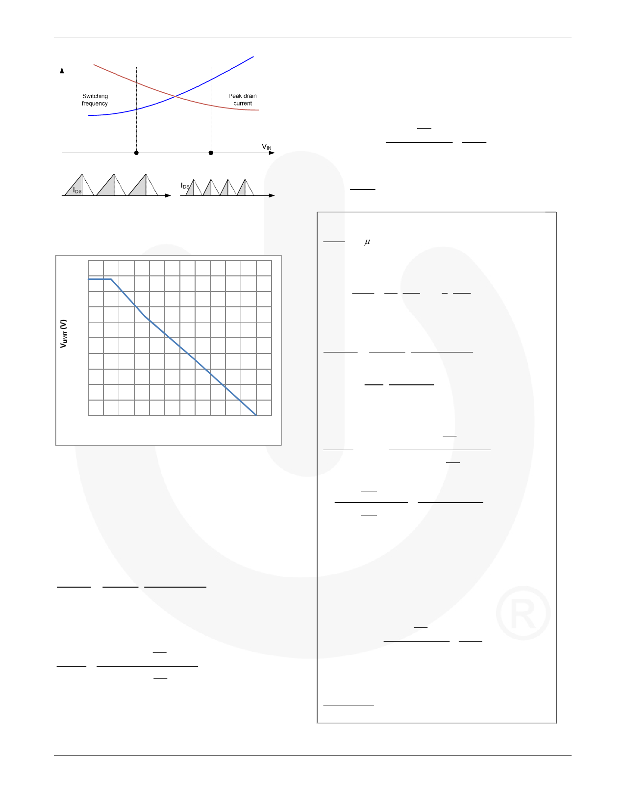
Figure 15. Switching Frequency and Peak Drain Current
Change as Input Voltage Increases
0.9
0.85
0.8
0.75
0.7
0.65
V
0.6
0.55
0.5
0.45
0.4
0
50 100 150 200 250 300 350 400 450 500 550 600
IDET (µA)
Figure 16. IDET-VLIMIT Curve
The relationship between IDET and VLIMIT in the linear region
(IDET=100~500µA) can be approximated as:
VLIMIT = −877 ⋅ IDET + 0.882
(37)
For a given output power, the ratio between drain peak
currents at low line and highline is obtained as:
I PK .L
DS
= VO.PFC.H ⋅ VO.PFC .L + VRO
I PK .H
DS
V V + V O.PFC.L O.PFC.H
RO
(38)
For a given output power, the ratio between pulse-by-pulse
current limit levels at low line and high line is obtained as:
VLIMIT .L
≅
−994 ⋅VO.PFC.L
NA
NP
+
RDET 1
VLIMIT .H
−994 ⋅VO.PFC.H
NA
NP
+ RDET1
(39)
To get a constant power limit, RDET1 should be determined
such that Equations (38) and (39) are equal. However, for
actual design, it is typical to use 105~120% of Equation
APPLICATION NOTE
(38), considering the pulse-by-pulse turn-off delay and
increased PFC output voltage ripple at low line.
Once the current limit threshold voltage is determined with
RDET1, the current sensing resistor value is obtained as:
VLIMIT
VO . PFC . L
= −877 ⋅ (
NA
NP
RDET 1
+0.7
+
0.7 ) + 0.882
RDET 2
(40)
The current sensing resistor value can be obtained from:
RCS 2
=
VLIMIT
I LIM
DS
(41)
(Design Example)
0.7 > 30μ A ,
RDET 2
RDET 2 < 23.3kΩ
Setting the OVP trip point at 22.5V,
KDET
=
RDET1
RDET 2
=
NA
NS
⋅ VOVP
2.5
−1 =
6 ⋅ 22.5 −1 = 8
6 2.5
Then RDET1 = KDET ⋅ RDET 2 < 196kΩ
I PK .L
DS
= VO.PFC.H
⋅ VO.PFC.L + VRO
I PK .H
DS
V V + V O.PFC.L O.PFC.H
RO
= 400 ⋅ 260 +130 = 1.13
260 400 +130
Using 116% of 1.13,
VLIMIT .L
= 1.31 ≅
−994VO.PFC.L
NA
NP
+ RDET1
VLIMIT .H
−994 ⋅VO.PFC.H
NA
NP
+ RDET1
=
−994 ⋅
260
6.8
+
RDET 1
=
−38, 018 +
RDET 1
−994
⋅
400
6.8
+
RDET
1
−58, 490 + RDET1
Then, RDET1 = 124.5kΩ and RDET 2 = 15.6kΩ
RDET1 and RDET2 are selected from the off-the-shelf
components as 120kΩ and 15kΩ, respectively.
Then, the pulse by pulse current limit threshold voltage
is obtained as:
VLIMIT
=
VO. PFC . L
−877 ⋅ (
NA
NP
RDET 1
+ 0.7
+
0.7 ) + 0.882
RDET 2
= 0.56V
To set current limit level at low line as 125% of IDSPK
0.56 = 0.2Ω
2.28 A ×1.25
© 2010 Fairchild Semiconductor Corporation
Rev. 1.0.1 • 8/24/10
11
www.fairchildsemi.com
Share Link: